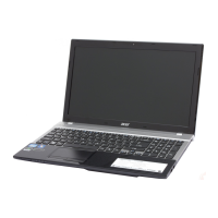
Do you have a question about the Acer Aspire V3-551 and is the answer not in the manual?
Summary of the computer's many features, including OS, platform, memory, display, and graphics.
Details exterior views: Top, Front, Left, Right, Base, identifying key components.
Explanation of touchpad operations and basic functions.
Explains keyboard keys, Windows keys, and hotkeys for system control.
Visual representation of the system's internal architecture and component connections.
Comprehensive technical specifications for the computer, including dimensions, power, and environment.
Guide to configuring system settings via the BIOS Setup Utility.
Details on BIOS menus: Information, Main, Security, Boot, Exit.
Selects boot device without entering BIOS setup.
Procedures for updating system BIOS via DOS or Windows.
Explains DMITools and LAN MAC EEPROM utility.
Procedures for unlocking HDD and managing BIOS passwords.
Steps for creating and using a USB flash crisis disk for recovery.
Diagram and list of connectors on the top side of the mainboard.
Diagram and list of connectors on the bottom side of the mainboard.
Diagram and list of connectors on the USB daughterboard.
Diagram and list of components on the power board.
Location and function of the CMOS jumper.
Guide to troubleshooting computer problems and using symptom tables.
Steps to diagnose and resolve system power-on problems.
Steps to diagnose and resolve no display or video problems.
Procedures for troubleshooting LCD screen image problems.
Troubleshooting steps for keyboard and touchpad failures.
Troubleshooting steps for internal speaker and microphone failures.
Troubleshooting steps for USB and wireless/Bluetooth failures.
Troubleshooting for 4-in-1 card, thermal, cosmetic, and other functions.
Troubleshooting BIOS problems, intermittent issues, and undetermined problems.
Introduction, tools, and maintenance flowchart for notebook servicing.
Steps for powering down, disconnecting, and preparing the system for maintenance.
Procedures for ODD and HDD module removal/installation.
Procedures for DIMM module removal/installation.
Procedures for WLAN module removal/installation.
Procedures for Palm Rest, Upper Case, Keyboard removal/installation.
Procedures for RTC Battery and Mainboard removal/installation.
Procedures for Thermal Module and CPU removal/installation.
Procedures for Speaker removal/installation.
Procedures for USB Module removal/installation.
Procedures for Power Board removal/installation.
Procedures for LCD Module, Bezel, Camera, Panel removal/installation.
Procedures for DC-In Cable and WLAN Antenna removal/installation.
Procedures for Microphone Module removal/installation.
Visual breakdowns of main, lower cover, upper cover, and LCD assemblies.
Comprehensive list of FRU parts with descriptions and part numbers.
List of screws used in the system with specifications.
Lists components and peripherals tested under Windows 7.
Describes Acer's online technical support services and resources.
| Storage | 500GB HDD |
|---|---|
| Weight | 2.6 kg (5.73 lbs) |
| Processor | AMD A8-4500M |
| RAM | 4GB DDR3 |
| Display | 15.6-inch HD (1366 x 768) LED-backlit |
| Graphics | AMD Radeon HD 7640G |
| Battery | 6-cell Li-ion |
| CPU | AMD A8-4500M |

