This document serves as a user guide for the Acer AT350 F3 server, providing essential information for experienced server technicians regarding its setup, operation, and troubleshooting.
System Setup
The guide begins by emphasizing the importance of proper system setup, offering notes and warnings for safe and effective installation. It advises users to contact a local certified Acer service representative before opening or removing any components to avoid voiding the warranty for parts damaged during replacement by non-certified technicians.
System Component Identification
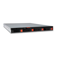
The manual provides detailed diagrams for identifying the server's components from both the front and rear views.
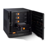
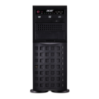
Front View:
The front panel features a Power On/Off button and a System Reset button for basic system control. Two USB 2.0 ports are available for connecting peripheral devices. The server includes three 5.25" drive bays, one of which can optionally house an optical drive. Below these, there are eight 3.5" hot-swappable drive bays, accessible behind a locking bezel, designed for easy hard drive management.
Rear View:
The rear view highlights the redundant power supplies, which enhance system reliability by providing backup power. Various Rear I/O Ports are present for external connections, including a COM Port, USB 2.0 ports, USB 3.0 ports, LAN1 and LAN2 for network connectivity, and a VGA Port for display output. An IPMI LAN Port is also included for remote management. Internally, the server features Rear Fans for cooling and PCIe Slots for expansion cards.
System Controls and Indicators
The guide details the functions of the front panel controls and indicators, crucial for monitoring the server's status and performing basic operations.
Controls:
- Power On/Off Button: This is the primary button for applying or turning off the main system power. Pressing it removes main power but keeps standby power supplied.
- System Reset Button: Used to reboot the system.
Indicators (LEDs):
- Power LED: Illuminates when power is supplied to the system's power supply, typically on during normal operation.
- HDD Activity LED: Flashes to indicate hard disk drive activity.
- LAN1 Network Activity LED: Flashes to indicate network activity on LAN1.
- LAN2 Network Activity LED: Flashes to indicate network activity on LAN2.
- Information LED: This multi-status LED provides critical system information:
- Continuously On (Red): Indicates an overheat condition.
- Fast Blinking Red (1 Hz): Signifies a fan failure.
- Slow Blinking Red (.25 Hz): Indicates a power fail.
- Solid Blue: Shows that the local UID button has been activated.
- Blinking Blue: Indicates that IPM/Remote UID has been activated.
- Power Fail LED: This LED is functional only when two power supply modules are installed. It illuminates to indicate that one of the power supply modules has failed.
Setting Up the System
The guide provides instructions for setting up the server, focusing on pre-installation requirements and checking package contents.
Pre-installation Requirements:
- Selecting a Site: Users are advised to choose a suitable site for maximum efficiency, considering factors such as proximity to a grounded power outlet, a clean and dust-free environment, a stable surface free from vibration, good ventilation, and isolation from electromagnetic fields produced by other electrical devices.
Checking the Package Contents:
- Users should verify that the system unit and accessory box are present. Any damaged or missing items should be reported to the dealer immediately. It is recommended to save the boxes and packing materials for future use.
Turning On the System
Detailed steps are provided for powering on the server after proper setup and peripheral connections.
Procedure:
- Press the power button. The system will display a welcome message and then a series of Power-On Self-Test (POST) messages, indicating whether the system is running correctly.
- Beyond POST messages, a lit blue power status indicator on the front panel and illuminated Num Lock, Caps Lock, and Scroll Lock indicators on the keyboard confirm the system's good condition.
Power-on Problems:
- If the system fails to boot, users should check for loosely connected external power cords, ensure proper connection from the power outlet to the power cord socket, verify power from the grounded power outlet, and check for loose or improperly connected internal power cables. For internal cable issues, a qualified technician's assistance is recommended.
- A crucial warning advises disconnecting all power cords from the electrical outlet before performing any internal cable checks.
Turning Off the System
The guide outlines two methods for shutting down the server: via software and via hardware.
Via Software (Windows OS):
- Press
<Ctrl> + <Alt> + <Delete> or click Start on the Windows taskbar.
- Select "Shut Down."
- Choose "Shut Down" from the drop-down menu, then click "OK."
Via Hardware:
- If software shutdown is not possible, press and hold the power button for at least four seconds. A quick press might only put the server into Suspend mode.
System Troubleshooting
This section focuses on resolving system issues, starting with basic resets and moving to more in-depth diagnostics.
Resetting the System:
- Soft boot: Press
<Ctrl> + <Alt> + <Del> to clear system memory and reload the operating system.
- Cold boot: Turn the system off and then on again to clear system memory, restart POST, and reload the operating system, halting power to all peripherals.
Initial System Startup Problems:
- A comprehensive checklist helps diagnose problems occurring at initial startup, which are often due to incorrect installation or configuration. Checks include:
- AC power availability and proper power supply module installation.
- Correct power cord connection to the power supply module socket and appropriate NEMA outlet.
- Proper connection and security of all peripheral cables.
- Confirmation that the system power button was pressed and the power-on indicator is lit green.
- Proper installation of device drivers.
- Correct formatting and configuration of hard disk drives.
- Correct BIOS configuration settings.
- Proper loading of the operating system.
- Compliance of hardware components with tested lists.
- Correct connection and security of internal cables.
- Proper seating of the processor in its mainboard socket.
- Correct placement of all standoffs to prevent shorts.
- Full seating of add-in expansion cards in their mainboard slots.
- Correct setting of all system jumpers and switch settings on add-in boards and peripheral devices.
- Users are advised to refer to manufacturers' documentation for these settings and ensure no conflicts exist between add-in boards.
Hardware Diagnostic Testing
This section provides a detailed approach to identifying hardware problems.
Checking the Boot-up Status:
- Caution: Before disconnecting any peripheral cables, turn off the system and all peripheral devices to prevent damage.
- Procedure:
- Turn off the system and all external peripheral devices.
- Disconnect all peripherals except the keyboard and display monitor.
- Ensure the system power cord is properly plugged into a grounded AC outlet and the power supply module cord socket.
- Verify the display monitor and keyboard are correctly connected.
- Turn on the display monitor.
- Set display brightness and contrast to at least two-thirds of their maximum range.
- If the OS loads from the hard drive, ensure no diskette or optical disc is in the drives.
- If the power indicator is lit, attempt to boot from a disc.
- Turn on the system.
- A note in Chinese translates to: "If the power indicator on the control panel does not light up, please refer to 'Power indicator does not light up'."
Verifying the Condition of the Storage Devices:
- During POST, the system checks for mass storage devices. Their activity indicators should briefly turn blue. Users should check indicators for hard drives, DVD-ROM drive, and any other 5.25" devices.
- If any indicator fails to light up, users should refer to the "Specific problems and corrective actions" section.
Specific Problems and Corrective Actions
This section lists common problems and their solutions.
Confirming Loading of the Operating System:
- If the operating system prompt does not appear after boot-up, users should consult the specific problems and corrective actions.
Power Indicator Does Not Light:
- Solutions: Ensure the power supply module is installed, the power cord is connected, the wall outlet has power, the front panel power indicator is lit, remove add-in cards to test booting (reinstalling one by one if successful), and verify proper installation and population of system-compliant memory modules and processors according to guidelines.
HDD Activity Indicator Does Not Light:
- Solutions: Ensure the drive is not disabled in BIOS Setup Utility, the drive is compatible, and the server's power budget has not been exceeded.
- Check that relevant switches and jumpers on the hard drive and backplane board are set correctly.
Optical Drive Activity Indicator Does Not Light:
- Solutions: Ensure SATA and power cables are connected, relevant switches and jumpers on the drive are set correctly, and the drive is properly configured.
Optical Drive Tray Cannot Be Ejected:
- Solution: Insert a paperclip into the small hole on the optical drive and gently pull the tray out.
Optical Drive Cannot Read a Disc:
- Solutions: Ensure the correct type of disc is used, the disc is properly seated, the disc is unscratched, and the drive's cables are connected.
Newly Installed Memory Modules Are Not Detected:
- Solutions: Ensure memory module specifications comply with system requirements, modules are populated according to guidelines, and modules are properly installed in their mainboard slots.
Network Activity Indicators Do Not Light:
- Solutions: Ensure correct network drivers are loaded and check if the network is idle.
Peripheral Device Connected to a USB Port Does Not Work:
- Solutions: Reduce the number of external devices connected to a USB hub and refer to the device's documentation.
Problem with the Software Program:
- Solutions: Verify software configuration, refer to installation/operation documentation, try a different software version, and contact the vendor if the software is defective.
No Characters Appear on the Display Monitor:
- Solutions:
- Check keyboard function (Num Lock indicator).
- Verify display monitor is plugged in and turned on, and switched to the correct system if using a switch box.
- Adjust brightness and contrast controls.
- Ensure the display monitor signal cable is connected.
- Test the display monitor with a different system.
- Remove all add-in cards to test booting (reinstalling one by one if successful).
- Ensure system-compliant memory modules and processors are properly installed and populated.
- If using an add-in video controller card:
- Verify the display monitor works with the onboard video controller.
- Verify the add-in video controller card is fully seated.
- Reboot the system.
- If still no characters, reboot again and note any beep codes during POST for technical assistance.
- Note: If POST emits no beep code and no characters appear, the display monitor or video controller may be defective; contact Acer support.
Notices
This section covers important safety and environmental information.
Information for Your Safety and Comfort:
- Safety Instructions: Read instructions carefully, keep the document, and follow all warnings.
- Turning the Product Off Before Cleaning: Unplug the product and use a damp cloth; avoid liquid or aerosol cleaners.
- CAUTION for Plug as Disconnecting Device:
- Install the power supply unit before connecting the power cord.
- Unplug the power cord before removing the power supply unit.
- If multiple power sources exist, unplug all power cords from the power supplies.
- CAUTION for Accessibility: Ensure the power outlet is easily accessible and close to the operator for quick disconnection.
Warnings:
- Do not use near water or place on unstable surfaces.
- Ventilation slots must not be blocked; avoid placing on soft surfaces or near heat sources.
- Never push objects into cabinet slots or spill liquids into the product.
- Avoid vibrating surfaces to prevent internal component damage or battery leakage.
- Do not use in vibrating environments that could cause short circuits or damage.
- This product is not suitable for visual display workplace devices according to German Ordinance §2.
Using Electrical Power:
- Operate from the power type indicated on the label; consult the dealer if unsure.
- Do not allow anything to rest on the power cord.
- Ensure extension cord ampere rating is not exceeded by plugged equipment.
- Do not overload power outlets; overall system load must not exceed 80% of branch circuit rating.
- The power supply has a three-wire grounded plug; ensure the power outlet is properly grounded.
- Warning: Using an ungrounded outlet can result in electric shock/injury.
- Note: Grounding also protects against noise from nearby electrical devices.
- Use only the supplied power supply cord set; replacements must meet specific UL/CSA/VDE requirements (detachable type, 4.6 meters max length).
Product Servicing:
- Do not attempt self-service; refer all servicing to qualified personnel.
- Unplug the product and seek qualified service when:
- The power cord or plug is damaged.
- Liquid was spilled into the product.
- The product was exposed to rain or water.
- The product was dropped or the case damaged.
- The product exhibits a distinct change in performance.
- The product does not operate normally after following instructions.
- Notes: Adjust only controls covered by instructions; improper adjustment can cause damage.
- The server should be in a restricted access location.
- Caution: Risk of explosion if battery is incorrectly replaced; use only the same or equivalent type. Dispose of used batteries according to manufacturer's instructions.
Disposal Instructions:
- Do not throw electronic devices into trash; recycle to minimize pollution.
- Refer to the Acer website for WEEE regulations information.
Regulations and Safety Notices
Laser Compliance Statement:
- The CD or DVD drive is a laser product.
- CLASS 1 LASER PRODUCT CAUTION: INVISIBLE LASER RADIATION WHEN OPEN. AVOID EXPOSURE TO BEAM.
- Translations of this warning are provided in French, German, Italian, Spanish, and Dutch.
Declaration of Conformity for EU Countries:
- Acer declares that this system complies with the essential requirements and relevant provisions of Directive 1999/5/EC.
List of Applicable Countries:
- The device must be used in strict accordance with country regulations. Further information is available on the specified Acer website.
- Note: Subsequent sections apply only to Class A systems.
FCC Notice Class A:
- This device complies with Part 15 of FCC rules for Class A digital devices, designed to provide reasonable protection against harmful interference in residential installations.
- If interference occurs, users are encouraged to reorient/relocate the receiving antenna, increase separation between devices, connect to a different circuit, or consult a technician.
Notice: Shielded Cables:
- All connections to other computing devices must use shielded cables to maintain FCC compliance.
Notice: Peripheral Devices:
- Only peripherals certified to comply with Class A limits should be attached. Non-certified peripherals may cause interference to radio and TV reception.
Caution:
- Changes or modifications not expressly approved by the manufacturer could void the user's authority to operate the computer.
Operation Conditions:
- This device complies with Part 15 of FCC Rules. Operation is subject to two conditions: (1) no harmful interference, and (2) acceptance of any interference received.
Notice: Canadian Users:
- This Class A digital apparatus complies with Canadian ICES-003.
- A French translation is provided: "Cet appareil numérique de la classe A est conforme a la norme NMB-003 du Canada."
Notice: BSMI (Taiwan):
- A warning in Chinese states that this is a Class A information product, and its use in a residential environment may cause radio frequency interference, requiring users to take appropriate countermeasures.