1-8 Disassembly Procedures
I/O Board Removal 0
Prerequisite:
Base Cover Removal
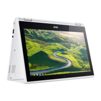
1. Find the USB board (C) on the base cover (Figure 1-8).
2. Disconnect the IO Board FFC (A) from the IO Board connecter (B) and remove it.
3. Remove the one (1) screw (D) securing the IO board in place (Figure 1-8).
Figure 1-8. IO Board Screw Location
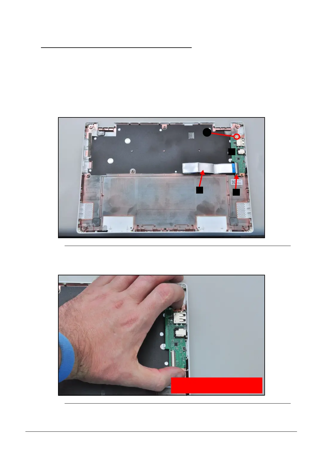
4. Remove the USB board from the base cover (Figure 1-9).
Figure 1-9. IO Board Removal
A
E
B
WEEE Annex VII Component:
I/O board
 Loading...