Disassembly Procedures 1-7
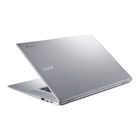
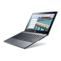
8. Carefully flip the left side of the base cover away from the system as shown in
Figure 1-6.
9. Disconnect the battery cable (A) from the mainboard connector (Figure 1-6).
10. Disconnect the IO board FFC (B) from the mainboard connector and gently peel it
away from the top assembly (Figure 1-6).
The IO Board FFC (Flexible Flat Cable) can be damaged if removed while the
mainboard connector is locked.
Figure 1-6. Base Cover Removal
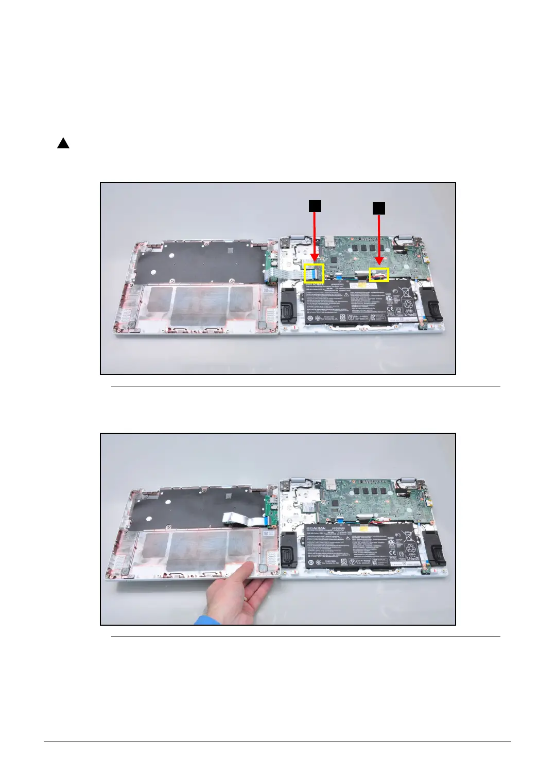
11. Remove the base cover (Figure 1-7).
Figure 1-7. Base Cover Removal

 Loading...