Disassembly Procedures 1-15
USB Board Removal 0
Prerequisite:
LCD Module Removal
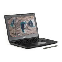
1. Locate the USB board (C) on the top assembly (Figure 1-19).
Figure 1-19. Component Location
2. Disconnect the 30-pin USB board FPC (B) from the mainboard connector (D) and the
USB board connector (A) and remove the 30-pin USB board FPC (Figure 1-20).
3. Disconnect the 40-pin USB board FPC (F) from the mainboard connector (G) and the
USB board connector (E) and remove the 40-pin USB board FPC (Figure 1-20).
4. Disconnect the USB board cable (J) from the USB board connector (H) (Figure 1-20).
5. Remove one (1) screw (K) securing the USB board in place (Figure 1-20).
Figure 1-20. USB Board Removal
 Loading...