Do you have a question about the Acer Veriton 5900Pro and is the answer not in the manual?
Provides a general introduction to the Veriton series desktop PCs and their business features.
Details the key hardware features of the system, including CPU, chipset, memory, and connectivity.
Specifies CPU socket, processor type, chipset components, and memory configurations.
Describes the onboard graphics solution, PCI/PCIe slots, and SATA IDE interfaces.
Details audio codec, LAN controller, and USB port specifications.
Explains system LED definitions and lists rear I/O connectors.
Illustrates the interconnections of major system components.
Provides a visual diagram of the main board, detailing connectors and jumpers.
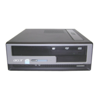
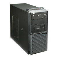
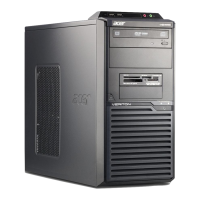
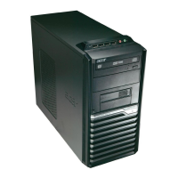
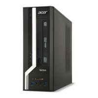
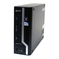
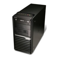
Guides users through the front panel components of the Veriton series computers.
Details the rear panel connectors and ports for various Veriton models.
Describes essential system peripherals like mouse, keyboard, and speakers.
Introduces Acer's proprietary utilities for system management and optimization.
Provides detailed specifications for system board chips, processor, and BIOS.
Explains ACPI support functions for device standby, global standby, and suspend modes.
Details Dual Channel technology, its benefits, and memory installation configurations.
Introduces the BIOS SETUP utility and explains control keys for navigation.
Details system product information and standard CMOS settings like date and time.
Covers advanced BIOS settings, chipset configurations, and CPU features.
Explains setup options for onboard IDE devices, USB controllers, and Super IO devices.
Monitors system health, voltages, temperatures, and controls CPU/system frequencies.
Covers loading defaults, setting passwords, saving, and exiting BIOS setup.
Lists necessary tools and provides safety guidelines before disassembling the computer.
Step-by-step guide for disassembling the Veriton 7900Pro, including component removal.
Step-by-step guide for disassembling the Veriton 6900Pro, including component removal.
Step-by-step guide for disassembling the Veriton 5900Pro, including component removal.
Overview of troubleshooting sections: POST, error messages, symptoms, and undetermined problems.
Explains the POST procedure, its components, and common checkpoint tasks.
Lists common POST error messages and symptoms with corresponding actions or FRUs.
Provides a systematic checklist for diagnosing and isolating problems not otherwise identified.
Details the main board layout, including numbered connectors and components.
Explains the function and settings for the CMOS jumper (CLR_CMOS).
Provides critical notes for ordering parts, handling defective units, and spare part list updates.
Illustrates exploded diagrams for Veriton 7900Pro, 6900Pro, and 5900Pro for part identification.