Do you have a question about the Acer Veriton M275 and is the answer not in the manual?
Summary of the computer's various features and specifications.
Illustration of the system's architecture and component interconnections.
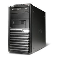
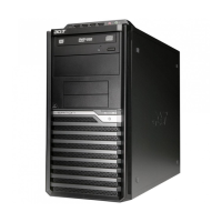
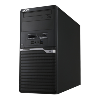
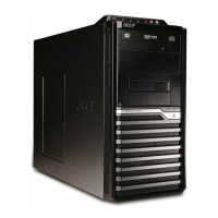
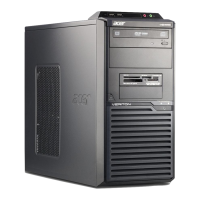
Details the system's interior and exterior components with labels.
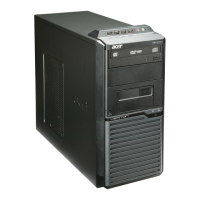
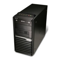
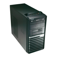
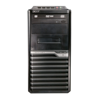
Describes components and ports on the front of the computer.
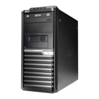
Describes components and ports on the rear of the computer.
Lists detailed technical specifications of system hardware.
Details CPU type, socket, and FSB specifications.
Provides information on BIOS version, type, size, and boot support.
Lists hotkeys for accessing and navigating BIOS setup.
Identifies main chipset components on the motherboard.
Details supported memory configurations and total capacity.
Specifies memory slot details, type, interface, and voltage.
Describes audio controller, channels, and compatibility.
Details SATA controller, bus, channels, and bootable CD-ROM support.
Lists USB port specifications, class, and connector quantity.
Outlines operating and non-operating environmental conditions.
Details power management states (S1-S5) for various devices.
Explains ACPI functions for device, global, and suspend modes.
Explains the purpose and conditions for running the CMOS setup utility.
Provides step-by-step instructions on how to access the CMOS setup.
Details keys and functions used to navigate the BIOS setup interface.
Describes main setup categories within the CMOS utility.
Displays non-configurable system information like CPU, memory, and serial number.
Covers system date, time, SATA port, and POST halt settings.
Manages boot order, boot protection, and other advanced BIOS settings.
Configures chipset features like EIST, XD Bit, and Virtualization Technology.
Controls onboard devices like SATA, USB, Audio, and LAN controllers.
Configures ACPI states, wake-up events, and restore on AC power loss.
Monitors system and CPU temperatures, fan speeds, and voltages.
Allows adjustment of system clock and spread spectrum settings.
Manages passwords and boot security options.
Resets BIOS parameters to their default values.
Saves configuration changes and exits BIOS setup.
Discards changes and exits BIOS setup.
Lists the necessary tools for disassembling the computer.
Outlines essential steps before starting the disassembly process.
Step-by-step guide to removing the computer's side panel.
Instructions for detaching the front bezel from the chassis.
Details removing the CPU heat sink and fan.
Explains how to safely remove and handle the CPU.
Provides instructions for removing RAM modules.
Guides through removing the graphics card.
Step-by-step instructions for removing the HDD.
Details how to remove the optical drive.
Instructions for detaching the system cooling fan.
Guides on removing the power supply unit.
Procedures for removing OBR and intrusion alarm components.
Instructions for removing COM and printer port cables.
Steps for removing the internal card reader.
Guides on detaching the internal speaker.
Detailed steps for removing the motherboard.
Instructions for removing the opposite side panel.
Guides on detaching front panel I/O and USB ports.
Instructions for removing power switch and LED cables.
Outlines process for performing diagnostic tests on Acer products.
Details procedures for checking power, external, and internal system status.
Explains beep code patterns and their corresponding error causes.
Describes system checkpoints and how to view them during POST.
Lists checkpoints for bootblock initialization phase.
Details checkpoints for bootblock recovery process.
Provides instructions for recovering the system BIOS using a USB drive.
Shows physical layout and numbering of motherboard components.
Explains how to set jumpers for system configuration.
Details specific jumper configurations, like Clear CMOS.
Provides pinouts and definitions for motherboard connectors and headers.
An illustrated breakdown of the computer system's components.
A list of field-replaceable units with descriptions and part numbers.