Do you have a question about the Acer Veriton M265 and is the answer not in the manual?
Lists operating systems and processor details.
Details chipset, PCB, memory, and expansion slots.
Details IDE, SATA, Audio, LAN, USB, and 1394 interfaces.
BIOS features, connectors, and power supply unit specifications.
Explains the setup utility and CMOS RAM.
Product info and standard CMOS parameter configuration.
BIOS, chipset, peripherals, power, PnP/PCI, frequency settings.
Health, defaults, password, saving, and exiting setup.
Lists tools, precautions, and initial power-off steps.
Step-by-step guides for removing external and internal components.
Lists topics for troubleshooting system issues.
Explains jumper settings and CMOS clearing procedure.
Details pin configurations for various system connectors.
Guidance on ordering FRU parts and exploded diagram.
Itemized list of FRUs with part numbers.
| Processor model | - |
|---|---|
| Processor family | Intel® Core™2 Duo |
| Processor frequency | 2.4 GHz |
| Processor manufacturer | Intel |
| Number of processors installed | 1 |
| Internal memory | 2 GB |
| Internal memory type | DDR2-SDRAM |
| Maximum internal memory | 4 GB |
| Memory layout (slots x size) | - GB |
| HDD interface | SATA |
| Optical drive type | DVD-RW |
| Card reader integrated | No |
| Total storage capacity | 320 GB |
| Intel segment tagging | Enterprise, Small Business |
| On-board graphics card | Yes |
| Discrete graphics card model | Intel® GMA 3100 |
| Operating system installed | FreeDOS |
| Compatible operating systems | Windows XP/7 FreeDOS |
| PS/2 ports quantity | 2 |
| USB 2.0 ports quantity | 6 |
| Firewire (IEEE 1394) ports | 0 |
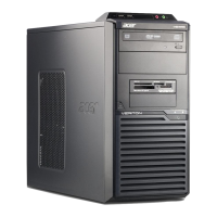
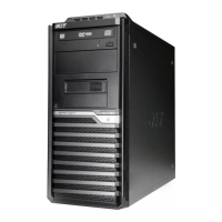
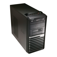
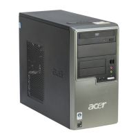
| Chassis type | Tower |
| Product color | Black |
| Product type | PC |
| Depth | 440 mm |
|---|---|
| Width | 180 mm |
| Height | 352 mm |