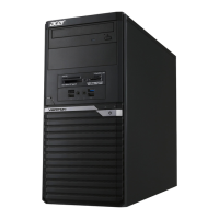
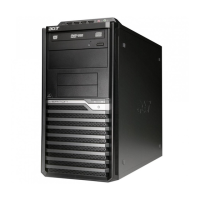
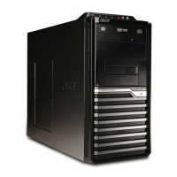
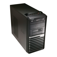
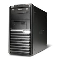
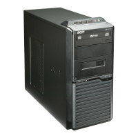
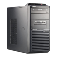
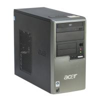
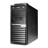
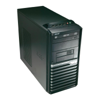
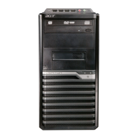
This document serves as a comprehensive recycling guide for the Veriton M6660G (VM6660G) and Veriton M4660G (VM4660G) desktop computers. It outlines the necessary procedures for disassembling the device, identifying components for selective treatment, and preparing the unit for recycling and disposal. The guide emphasizes safety precautions and provides detailed, step-by-step instructions for component removal.
The primary function of this guide is to facilitate the safe and environmentally responsible end-of-life management of the Veriton M6660G and M4660G systems. It enables users and recycling facilities to systematically dismantle the computers, ensuring that hazardous materials are handled appropriately and valuable resources are recovered. By following the outlined procedures, the environmental impact associated with electronic waste is minimized, aligning with WEEE (Waste Electrical and Electronic Equipment) directives for selective treatment of certain components.
Usage features of this guide include clear, illustrated instructions for each disassembly step. The document begins with essential safety guidelines, advising users to disconnect all power sources, ground themselves to prevent electrostatic discharge, and remove any metal objects from their hands. It also warns against forceful removal of components and provides guidance on disconnecting cables correctly, especially those with locking tabs. These precautions are crucial for preventing injury and damage during the disassembly process. The guide specifies recommended equipment, such as a wrist grounding strap, conductive mat, various screwdrivers (flat, Philips, Polydrive), plastic tweezers, and a flat plastic pry, ensuring that users have the right tools for the job.
Before commencing disassembly, the guide provides pre-disassembly instructions, which include placing the system on a stable work surface, removing the AC power cord and all other cables from the system, and ensuring the system is completely powered off. These preliminary steps are vital for safety and to prepare the device for the subsequent removal procedures.
The disassembly process is broken down into logical sections, starting with the removal of the chassis door. This involves unscrewing two screws from the rear of the chassis and then sliding the left side cover off. This initial step grants access to the internal components of the computer.
Next, the guide details the removal of the Optical Disc Drive (ODD) and card reader module. For the ODD, users are instructed to disconnect the SATA and power cables from the rear of the drive, remove two screws securing it within its cage, and then slide the ODD out. The card reader module removal involves disconnecting several cables from the motherboard, including the CR cable, intrusion cable, INT SPK cable, audio cable, and USB cable. A diagram clearly labels the connection points on the motherboard (Intrusion, F-USB1, F-USB2, INT_SPK, F_AUDIO). After disconnecting the cables, a green lock must be slid, allowing the card reader module to be pulled out.
The Hard Disk Drive (HDD) removal is also thoroughly explained. This involves disconnecting SATA and power cables from both the motherboard and the HDD itself. The guide shows how to take out the HDD from its cage and then rotate the mobile rack to fully remove the HDD.
The system fan removal requires unscrewing four screws that secure the fan and then disconnecting its power connector from the motherboard.
For the VGA card, the guide instructs users to remove a screw, rotate the PCI cover, and then carefully remove the VGA card from its slot.
The Power Supply Unit (PSU) removal involves unscrewing four screws fixed in the rear chassis and disconnecting all power connectors from the motherboard. A latch then needs to be pushed to release and take out the PSU.
The most intricate part of the disassembly, the removal of the Motherboard, Memory (MEM), CPU, Cooler, WLAN, SSD, and RTC Battery, is covered in detail. This section begins with disconnecting various front panel cables from the motherboard, specifically F_U31C1, F_U31C2, and USB3F1, along with other front panel cables. Eight screws securing the motherboard must then be removed. The guide highlights circuit boards larger than 10 cm² with a yellow rectangle, indicating they are WEEE Annex VII components requiring selective treatment.
Memory modules are removed by releasing four latches. The CPU cooler removal involves unscrewing four screws and disconnecting its power cable from the motherboard. The CPU itself is removed by manipulating a lever mechanism on its socket. The M.2 SSD is removed by unscrewing a single screw. Finally, the RTC battery is removed, and like the larger circuit boards, it is highlighted as a WEEE Annex VII component, emphasizing its need for selective treatment due to its chemical composition.
Maintenance features of this guide extend beyond mere disassembly. It includes a "Troubleshooting" section, which provides information on the Power-On Self-Test (POST) and a list of POST error messages. This section is designed to help users diagnose system problems before or during the recycling process. It explains that POST is a BIOS procedure that initializes and diagnoses system components upon startup. If errors occur, POST displays messages or halts the system. The guide lists main components diagnosed by POST, such as the microprocessor, DMA controller, interrupt system, timers, ROM, RAM, CMOS RAM, onboard parallel interface, hard disk interface, keyboard, auxiliary device controllers, and I/O ports.
The "POST Error Messages List" table is a key troubleshooting tool. It correlates specific BIOS messages (e.g., "BIOS ROM checksum error," "CMOS Battery Failed," "Hard disk(s) diagnosis fail") with their likely causes and recommended actions or Field Replaceable Units (FRUs). For instance, a "BIOS ROM checksum error" suggests corrupt BIOS code and recommends contacting the system dealer for a replacement. A "CMOS Battery Failed" message indicates a non-functional CMOS battery, also requiring replacement. This section is invaluable for identifying and addressing issues that might prevent a system from booting or operating correctly, even if the ultimate goal is recycling.
The guide also includes "Exploded Diagrams" which visually represent the system's components and their relative positions, aiding in identification during disassembly. A "FRU (Field Replaceable Unit) List" is provided, advising users to contact their local service center for obtaining parts or replacing their device, although for a recycling guide, this primarily serves to identify components that might be individually replaced or recycled.
Finally, the document offers instructions on "To update your software" and "To remove your personal data." While software updates are less relevant for recycling, the data removal section is critically important. It provides three options for securely removing personal data:
- Using Windows settings: Navigate to Start > Settings > Update & Security > Recovery, and select "Get started" under "Reset this PC."
- From the sign-in screen: Restart the PC, then press and hold the Shift key while selecting the Power icon > Restart. After restarting, choose Troubleshoot > Reset this PC.
- From the desktop: Select Start, then press and hold the Shift key while selecting the Power icon > Restart. After restarting, choose Troubleshoot > Reset this PC.
These data removal steps are essential to protect user privacy before the device is recycled or disposed of, ensuring that sensitive information is not compromised.
In summary, this recycling guide is a comprehensive resource for the Veriton M6660G and M4660G, designed to facilitate safe, efficient, and environmentally sound end-of-life processing. It combines detailed disassembly instructions with crucial safety warnings, troubleshooting information, and data security protocols, making it an indispensable tool for anyone involved in the recycling or disposal of these computer systems.