
M
Molly YoungJul 28, 2025
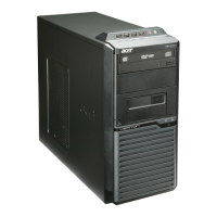
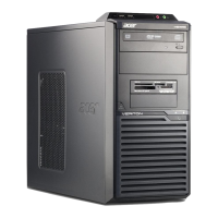
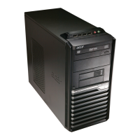
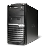
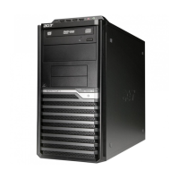
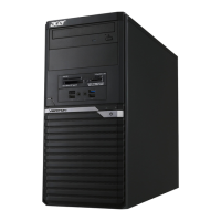
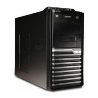
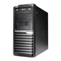
What to do if my Acer Veriton M430 will not power on?
- RRicardo WilsonJul 28, 2025
If your Acer Desktop won't power on, first ensure the power cable is securely connected to both the system and the AC power source. Also, verify that the voltage selector switch is set to the correct voltage.