EasyManua.ls Logo

Acer Veriton 5800 - User Manual

Acer Veriton 5800
106 pages
Print Icon
To Next Page IconTo Next Page
Loading...
I
Chapter 1 System Specification 1
Overview . . . . . . . . . . . . . . . . . . . . . . . . . . . . . . . . . . . . . . . . . . . . . . . . . . . . . . . . . . . .1
Features . . . . . . . . . . . . . . . . . . . . . . . . . . . . . . . . . . . . . . . . . . . . . . . . . . . . . . . . . . . .2
System Block Diagram . . . . . . . . . . . . . . . . . . . . . . . . . . . . . . . . . . . . . . . . . . . . . . . . .5
Mainboard Placement . . . . . . . . . . . . . . . . . . . . . . . . . . . . . . . . . . . . . . . . . . . . . . . . . .6
Rear I/O Port . . . . . . . . . . . . . . . . . . . . . . . . . . . . . . . . . . . . . . . . . . . . . . . . . . . . . . . . .7
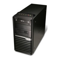
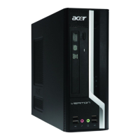
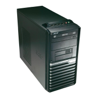
Veriton 5800 Front Panel . . . . . . . . . . . . . . . . . . . . . . . . . . . . . . . . . . . . . . . . . . . . . . .8
Veriton 6800 Front Panel . . . . . . . . . . . . . . . . . . . . . . . . . . . . . . . . . . . . . . . . . . . . . . .9
Veriton 7800 Front Panel . . . . . . . . . . . . . . . . . . . . . . . . . . . . . . . . . . . . . . . . . . . . . .10
Veriton 5800 Rear Panel . . . . . . . . . . . . . . . . . . . . . . . . . . . . . . . . . . . . . . . . . . . . . .11
Veriton 6800 Rear Panel . . . . . . . . . . . . . . . . . . . . . . . . . . . . . . . . . . . . . . . . . . . . . .12
Veriton 7800 Rear Panel . . . . . . . . . . . . . . . . . . . . . . . . . . . . . . . . . . . . . . . . . . . . . .13
System Peripherals . . . . . . . . . . . . . . . . . . . . . . . . . . . . . . . . . . . . . . . . . . . . . . . . . . .14
Acer eRecovery . . . . . . . . . . . . . . . . . . . . . . . . . . . . . . . . . . . . . . . . . . . . . . . . . . . . .16
Acer disc-to-disc recovery . . . . . . . . . . . . . . . . . . . . . . . . . . . . . . . . . . . . . . . . . . . . .18
Hardware Specifications and Configurations . . . . . . . . . . . . . . . . . . . . . . . . . . . . . . .19
Power Management Function ( ACPI support function) . . . . . . . . . . . . . . . . . . . . . . .26
Dual Channel . . . . . . . . . . . . . . . . . . . . . . . . . . . . . . . . . . . . . . . . . . . . . . . . . . . . . . .27
Chapter 2 System Utilities 29
Entering Setup . . . . . . . . . . . . . . . . . . . . . . . . . . . . . . . . . . . . . . . . . . . . . . . . . . . . . .30
Product Informatoin . . . . . . . . . . . . . . . . . . . . . . . . . . . . . . . . . . . . . . . . . . . . . . . . . .32
Standard CMOS Features . . . . . . . . . . . . . . . . . . . . . . . . . . . . . . . . . . . . . . . . . . . . .33
Advanced BIOS Features . . . . . . . . . . . . . . . . . . . . . . . . . . . . . . . . . . . . . . . . . . . . . .36
Advanced Chipset Features . . . . . . . . . . . . . . . . . . . . . . . . . . . . . . . . . . . . . . . . . . . .40
Integrated Peripherals . . . . . . . . . . . . . . . . . . . . . . . . . . . . . . . . . . . . . . . . . . . . . . . .41
Power Management Setup . . . . . . . . . . . . . . . . . . . . . . . . . . . . . . . . . . . . . . . . . . . . .44
PnP/PCI Configuration . . . . . . . . . . . . . . . . . . . . . . . . . . . . . . . . . . . . . . . . . . . . . . . .46
PC Health Status . . . . . . . . . . . . . . . . . . . . . . . . . . . . . . . . . . . . . . . . . . . . . . . . . . . .49
Frequency Control . . . . . . . . . . . . . . . . . . . . . . . . . . . . . . . . . . . . . . . . . . . . . . . . . . .51
Load Default Settings . . . . . . . . . . . . . . . . . . . . . . . . . . . . . . . . . . . . . . . . . . . . . . . . .52
Set Supervisor/User Password . . . . . . . . . . . . . . . . . . . . . . . . . . . . . . . . . . . . . . . . . .53
Save & Exit Setup . . . . . . . . . . . . . . . . . . . . . . . . . . . . . . . . . . . . . . . . . . . . . . . . . . . .54
Exit Without Saving . . . . . . . . . . . . . . . . . . . . . . . . . . . . . . . . . . . . . . . . . . . . . . . . . . .55
Chapter 3 Machine Disassembly and Replacement 57
General Information . . . . . . . . . . . . . . . . . . . . . . . . . . . . . . . . . . . . . . . . . . . . . . . . . .58
VT 5800 Disassembly Procedure . . . . . . . . . . . . . . . . . . . . . . . . . . . . . . . . . . . . . . . .59
VT 6800 Disassembly Procedure . . . . . . . . . . . . . . . . . . . . . . . . . . . . . . . . . . . . . . . .64
VT 7800 Disassembly Procedure . . . . . . . . . . . . . . . . . . . . . . . . . . . . . . . . . . . . . . . .69
Chapter 4 Troubleshooting 75
Power-On Self-Test (POST) . . . . . . . . . . . . . . . . . . . . . . . . . . . . . . . . . . . . . . . . . . . .76
POST Error Messages List . . . . . . . . . . . . . . . . . . . . . . . . . . . . . . . . . . . . . . . . . . . . .82
Error Symptoms List . . . . . . . . . . . . . . . . . . . . . . . . . . . . . . . . . . . . . . . . . . . . . . . . . .84
Undetermined Problems . . . . . . . . . . . . . . . . . . . . . . . . . . . . . . . . . . . . . . . . . . . . . . .89
Connectors Introduction . . . . . . . . . . . . . . . . . . . . . . . . . . . . . . . . . . . . . . . . . . . . . . .91
Chapter 5 Jumper and Connector Locations 91
Chapter 6 FRU (Field Replaceable Unit) List 101
Exploded Diagram . . . . . . . . . . . . . . . . . . . . . . . . . . . . . . . . . . . . . . . . . . . . . . . . . .102
Table of Contents

Table of Contents

Other manuals for Acer Veriton 5800

Questions and Answers

  • C
    Curtis JordanAug 19, 2025
    What to do if my Acer Veriton 5800 shows 'Keyboard Error Or No Keyboard Present'?
    • X
      xmillerAug 19, 2025
      If your Acer Desktop displays the error 'Keyboard Error Or No Keyboard Present', it means the system can't initialize the keyboard. Ensure the keyboard is correctly attached and that no keys are being pressed during the Power-On Self-Test (POST).
  • C
    Christopher ValenciaAug 21, 2025
    Why does my Acer Desktop say 'CMOS Checksum Error - Defaults loaded'?
    • J
      Jason RiceAug 21, 2025
      If your Acer Desktop displays 'CMOS Checksum Error - Defaults loaded', it indicates that the CMOS checksum is incorrect, causing the system to load default settings. This might mean the CMOS has become corrupt. You should check the battery and replace it if necessary.
  • J
    John PhillipsAug 23, 2025
    What to do if my Acer Desktop shows 'HARD DISK INSTALL FAILURE'?
    • K
      Kathleen CookAug 25, 2025
      If your Acer Desktop displays 'HARD DISK INSTALL FAILURE', it means the system cannot find or initialize the hard drive controller or the drive. Make sure the controller is correctly installed. If no hard drives are installed, ensure the Hard Drive Selection in Setup is set to NONE.
  • N
    Nicole ReidAug 26, 2025
    How to fix 'BIOS ROM checksum error - System halted' on Acer Desktop?
    • G
      gonzalesalexisAug 26, 2025
      If your Acer Desktop displays the error 'BIOS ROM checksum error - System halted', it means that the checksum of the BIOS code in the BIOS chip is incorrect, indicating the BIOS code may have become corrupt. Contact your system dealer to replace the BIOS.
  • S
    Suzanne ObrienAug 28, 2025
    What does 'Keyboard is locked out - Unlock the key' mean on Acer Veriton 5800 Desktop?
    • L
      Lisa HouseAug 28, 2025
      If your Acer Desktop displays 'Keyboard is locked out - Unlock the key', it usually means that one or more keys were pressed during the keyboard tests. Make sure no objects are resting on the keyboard.
  • S
    Sabrina JohnsonAug 30, 2025
    What to do if my Acer Desktop says 'Floppy disk(s) fail'?
    • V
      Veronica EdwardsAug 30, 2025
      If your Acer Desktop reports 'Floppy disk(s) fail', it indicates that the system cannot find or initialize the floppy drive controller or the drive. Make sure the controller is installed correctly. If no floppy drives are installed, ensure the Diskette Drive selection in Setup is set to NONE or AUTO.
  • J
    Jason JohnsonSep 1, 2025
    What does 'Hard disk(s) diagnosis fail' mean on Acer Veriton 5800?
    • J
      Judy HoodSep 1, 2025
      If your Acer Desktop displays 'Hard disk(s) diagnosis fail', it means one or more hard disks returned an error when the diagnostics ran.
  • M
    Marcus DeanSep 3, 2025
    What to do if Acer Desktop says 'Display switch is set incorrectly'?
    • A
      Alexis YoungSep 3, 2025
      If your Acer Desktop displays 'Display switch is set incorrectly', it means that the display switch on the motherboard is set incorrectly (either monochrome or color). Determine the correct setting, then either turn off the system and change the jumper, or enter Setup and change the Video selection.
  • E
    Erin LewisSep 5, 2025
    Why is the processor fan not running on my Acer Veriton 5800 Desktop?
    • W
      William LoweSep 6, 2025
      If the processor fan on your Acer Desktop is not running but the power supply fan is, ensure the system is not in power saving mode. With the system powered on, measure the voltage of the processor fan connector; it should read +12Vdc. If the reading is normal but the fan still doesn't work, replace the fan.
  • S
    Sarah WalterSep 7, 2025
    What does 'CMOS Battery Failed' mean on Acer Veriton 5800?
    • K
      kimberly89Sep 7, 2025
      If your Acer Desktop displays 'CMOS Battery Failed', it means the CMOS battery is no longer functional. Contact your system dealer for a replacement BIOS.

Summary

Chapter 1 System Specification

Overview

Provides a general introduction to the VTX800 series desktop PCs and their features.

Features

Details the key hardware specifications including CPU, Chipset, Memory, and Slots.

Hardware Specifications and Configurations

Presents detailed technical specifications for the System Board, Processor, and BIOS.

Chapter 2 System Utilities

Entering Setup

Guide on how to access and navigate the Award BIOS CMOS Setup Utility.

Standard CMOS Features

Covers basic system settings such as date, time, and IDE configuration.

Advanced BIOS Features

Details advanced system settings for boot priority, security, and other configurations.

Save & Exit Setup

Explains how to save configuration changes and exit the BIOS setup utility.

Chapter 3 Machine Disassembly and Replacement

General Information

Provides essential precautions and tools needed before disassembling the computer.

VT 5800 Disassembly Procedure

Step-by-step guide for disassembling the VT 5800 model computer.

VT 6800 Disassembly Procedure

Step-by-step guide for disassembling the VT 6800 model computer.

VT 7800 Disassembly Procedure

Step-by-step guide for disassembling the VT 7800 model computer.

Chapter 4 Troubleshooting

Power-On Self-Test (POST)

Explains the POST process, system initialization, and error detection during startup.

POST Error Messages List

Lists and describes POST error messages and their potential actions or FRU replacements.

Error Symptoms List

Helps diagnose problems by matching observed symptoms to potential causes and solutions.

Chapter 5 Jumper and Connector Information

Connectors Introduction

Provides an overview and diagrams of the mainboard's connectors and pin definitions.

Chapter 6 FRU (Field Replaceable Unit) List

Exploded Diagram

Visual representation of the computer's components with item numbers for identification.

Acer Veriton 5800 Specifications

General IconGeneral
BrandAcer
ModelVeriton 5800
CategoryDesktop
LanguageEnglish

Related product manuals