Installation and Operation Instructions
Part # A/CTE-50, A/CTE-250,
A/CTV-50, A/CTV-250
AUTOMATION COMPONENTS, INC Version : 1.0
2305 Pleasant View Road Page 1 of 3 I0000141
Middleton, Wisconsin 53562 (888) 967-5224
www.workaci.com
Please Read Instructions Carefully Before Installation!
Safety
This product is not intended to be used for Life or Safety applications.
This product is not intended for use in any hazardous or classified locations.
Disconnect and lock out all power sources before installation as severe injury or death may result from electrical
shock due to contact with high voltage wires.
Installation
Disconnect and lock out all power sources before installation as severe injury or death may result from electrical shock due to
contact with high voltage wires. Make sure that all installations are in compliance with all national and local electrical codes.
Only qualified individuals that are familiar with codes, standards, and proper safety procedures for high-voltage installations
should attempt installation. The current sensor will not require external power, since the power for the current sensor is
induced from the conductor being monitored.
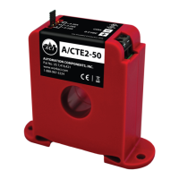
The A/CTE & A/CTV Series Analog Current Sensors should be used on Insulated Conductors Only! The current sensors may
be mounted in any position using the (2) #8 x 3/4” Tek screws and the mounting holes in the base or snapped directly on to the
35mm DIN rail (See Figures 1 & 2 below). Leave a minimum distance of 1” (3 cm) between the current sensor and any other
magnetic devices such as contactors and transformers.
3X
IND.CONT.EQ.
C
LISTED
US
3JHX
Automation Components, Inc.
Middleton, WI
A/CTE-50
ACI
US
C
LISTED
3JHX
IND.CONT.EQ.
Automation Components, Inc.
Middleton, WI
A/CTE-50
ACI
3X
Figure 1: Sensor Placed on Rail Figure 2: Sensor Removed From Rail
Wiring
ACI recommends the use of a 2 conductor 16 to 22 AWG shielded cable, or copper wire only for all Analog current sensor
installations. A maximum wire length of less than 30 meters (98.4 feet) should be used between the A/CTE and A/CTV series
current sensors and the Building Management System or controller. Note: When using a shielded cable, be sure to connect only
(1) end of the shield to ground at the controller. Connecting both ends of the shield to ground may cause a ground loop. When
removing the shield from the sensor end, make sure to properly trim the shield so as to prevent any chance of shorting. The
current sensors terminals are polarity sensitive and represent a linear 0 to 5 or 0 to 10 VDC output signal. The recommended
torque to be used on the terminal block connections is 0.67 Nm or 5.93 in-lbs. The aperture (hole) size of the current sensor is
0.75” (1.90 cm) and will accept a maximum cable diameter of 350 MCM’s.