Chapter3 Installation / 17
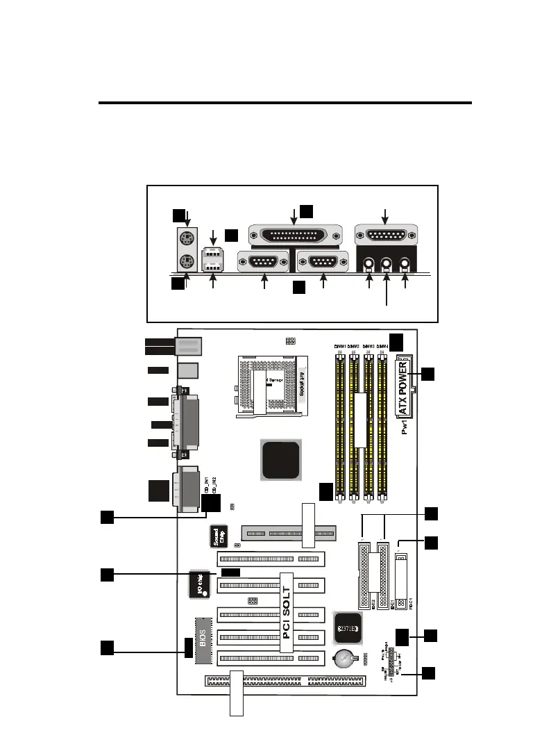
EXTERNAL CONNECTORS
Both Ribbon cable and Connectors on board are with direction signs
to avoid that user insert wrong directions. On other hand, the ribbon
cables should always be connected with the red stripe on the pin 1
of side of the connector.
ISA SLOT1
FAN1
down :
up
K/B
:Mouse
USB
COM1
COM2
Printer
MIDI/
GAME/
AUDIO
FAN2
FAN 3
JP1
IDE
FDC
SOCKET
J3
LAN
82443BX
JP5
1
IR
J2
12
PCI1PCI2PCI3PCI5 PCI4
ISA SOLT
AGP1
AGP SOLT
J6
1
JP7
1
1
JP6
DIMM
FAN 1,2,3
Connector
IR Port
Wake On
LAN
ATX Power
Connector
Floppy
Driver Connec-
tor
CD Audio
Connector
PS/2 Keyboard
PS/2 KeyboardPS/2 Keyboard
PS/2 Keyboard
(6-pin Female)
(6-pin Female)(6-pin Female)
(6-pin Female)
COM1
COM1COM1
COM1
COM2
COM2COM2
COM2
SPEAKER
SPEAKERSPEAKER
SPEAKER
MIC
MICMIC
MIC
PS/2 Mouse
PS/2 MousePS/2 Mouse
PS/2 Mouse
USB1
USB1USB1
USB1
USB2
USB2USB2
USB2
(25-pin Female)
(25-pin Female)(25-pin Female)
(25-pin Female)
(15-pin Female)
(15-pin Female)(15-pin Female)
(15-pin Female)
1
2
3
4
5
6
7
9
10
11
12
13
IDE Connec-
tor
8
PANEL