ƲƷ
CAUTION!
Do not purge the air with refrigerants but use a vacuum pump to vacuum the installation! There is no extra refrigerant in
theoutdoor unit for air purging!
ƴ.1.5 Checking the Pipe Connections for Gas Leaking
ƴ.1.6 Heat Insulation on the Pipe Joints (Indoor Side Only)
ƴ.1.7 Vacuum and Gas Leakage Inspection
ƴ.1.7.1 Vacuum
For both indoor and outdoor unit side, check the joints for gas leaking by the use of a gas leakage
detector without fail when the pipes are connected.
(1) Remove the caps of the liquid valve, gas valve and also the service port.
(2) Connect the hose at the low pressure side of the manifold valve assembly to the service port of
the unit’s gas valve, and meanwhile the gas and liquid valves should be kept closed in case of
refrigerant leak.
(3) Connect the hose used for evacuation to the vacuum pump.
(4) Open the switch at the lower pressure side of the manifold valve assembly and start the vacuum
pump. Meanwhile, the switch at the high pressure side of the manifold valve assembly should be
kept closed, otherwise evacuation would fail.
(5) The evacuation duration depends on the unit’s capacity, generally, 20 minutes for the 18k units,
30 minutes for the 24k/30k/36k units, 45 minutes for the 42k/48k units. And verify if the pressure
gauge at the low pressure side of the manifold valve assembly reads -1.0MPa (145psig), if not, it
indicates there is leak somewhere. Then, close the switch fully and then stop the vacuum pump.
(6) Wait for some time to see if the system pressure can remain unchanged, 3 minutes for the
18k/24k units, 10 minutes for the 30k/36k/42k/48k units. During this time, the reading of the
pressure gauge at the low pressure side can not be larger than 0.005MPa (0.72psig).
(7) Slightly open the liquid valve and let some refrigerant go to the connection pipe to balance the
pressure inside and outside of the connection pipe, so that air will not come into the connection
pipe when removing the hose. Note that the gas and liquid valve can be opened fully only after the
manifold valve assembly is removed.
(8) Place back the caps of the liquid valve, gas valve and also the service port.
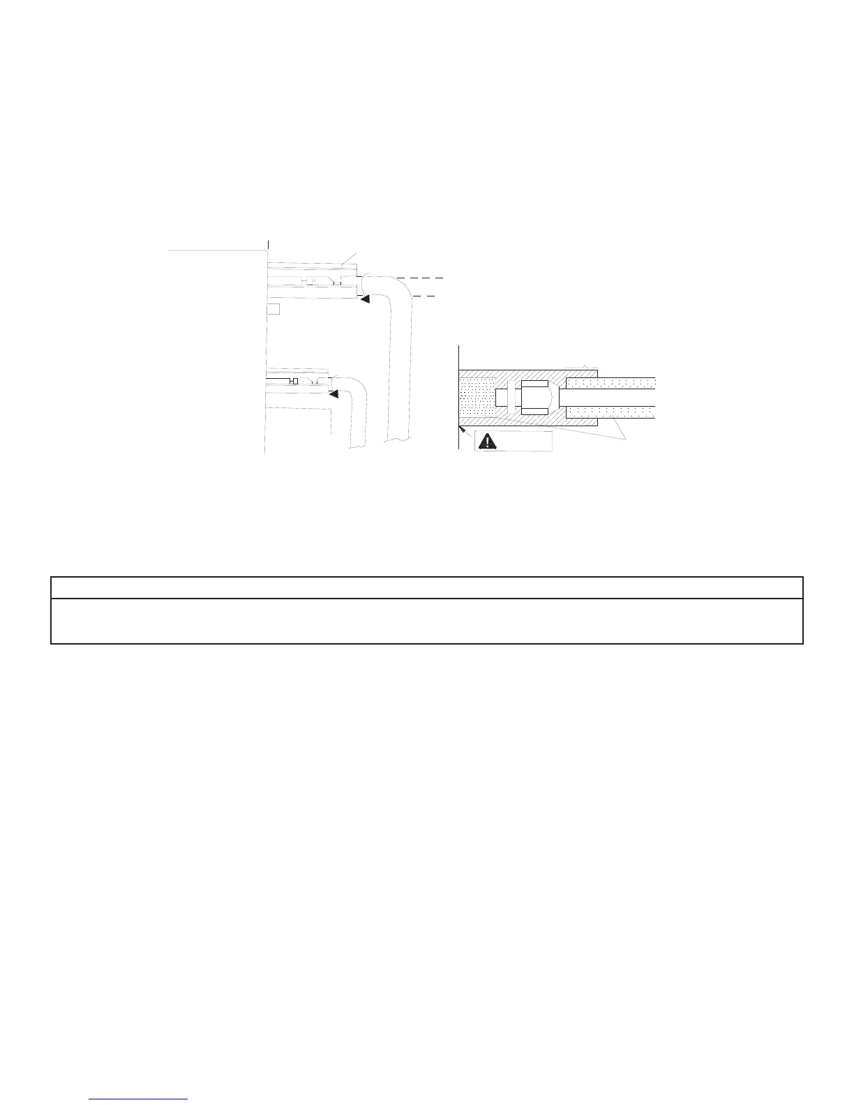
Stick coupler heat insulation (large and small) to the place where connecting pipes.
Front outlet
Coupler heat
insulation (small)
on the pipe
Liquid pipe
Gas pipe
Reference A
Coupler heat insulation
(large) on the pipe
Heat insulation pipe
Reference A:
Cover this portion with heat
insulating material also without fail
No gap
Figure 3-2-3



 To Next Page