36
A5MSY-2010 Application Information
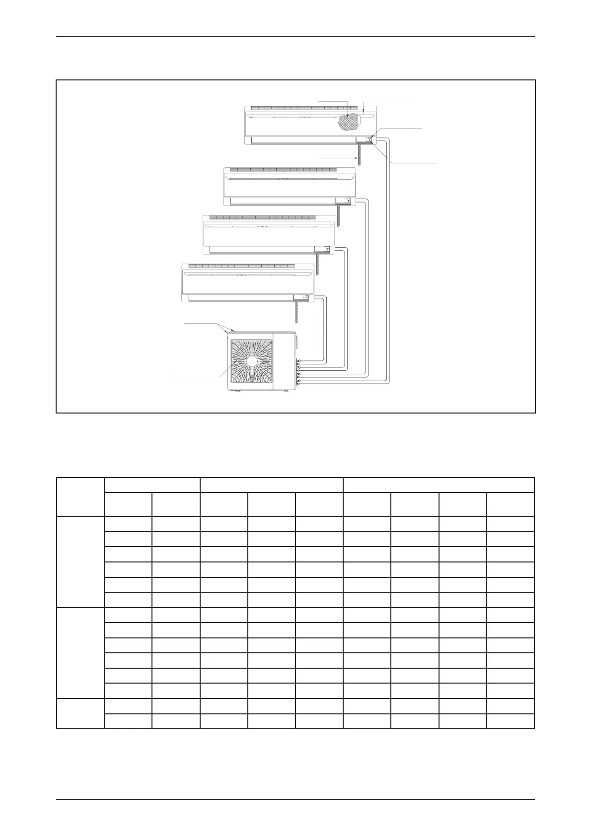
INSTALLATION OF OUTDOOR UNIT
AIR FILTER
FRONT FRAME
SIGNAL RECEIVER
INDICATOR LIGHT &
ON/OFF SWITCH
DRAIN HOSE
INDOOR UNIT
RETURN AIR
AIR DISCHARGE NOZZLE
OUTDOOR UNIT
Indoor Unit Combination for Outdoor Unit A5MSY20BR, A5MSY25BR and A5MSY30BR
Indoor Units with model name A5WMY10JR, A5WMY15JR and A5WMY20JR could be coupled with this
outdoor unit.
The following table shows the possible coupling combinations available.
No. of
indoor
units
A5MSY20BR A5MSY25BR A5MSY30BR
Indoor A Indoor B Indoor A Indoor B Indoor C Indoor A Indoor B Indoor C Indoor D
2
10 10 10 10 - 10 10 - -
10 15 10 15 - 10 15 - -
15 15 10 20 - 10 20 - -
10 20 15 15 - 15 15 - -
15 20 15 20 - 15 20 - -
- - 20 20 - 20 20 - -
3
- - 10 10 10 10 10 10 -
- - 10 10 15 10 10 15 -
- - 10 10 20 10 10 20 -
- - 10 15 15 10 15 15 -
- - 10 15 20 10 15 20 -
- - 15 15 15 15 15 15 -
4
-----10101010
-----10101015
For further details on operation combinations, total capacity and other technical specifi cations, please refer to
the technical manual.
* Multi-split inverter outdoor unit should not be coupled to one indoor unit only