11
Application Information A5LCY-E-2010
Indoor Unit Installation
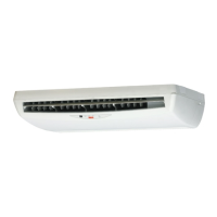
1. Installing the mounting plate
The mounting plate should be installed on a wall which can support the weight of the indoor unit.
1) Temporarily secure the mounting plate to the wall, make sure that the panel is completely level, and mark
the boring points on the wall.
2) Secure the mounting plate to the wall with screws.
Recommended mounting plate retention spots and dimensions
•
770
Use tape measure
as shown.
Position the end of
a tape measure at
Keep here the piece cut out
from the unit for piping
unit: mm
Gas pipe end
* The removed pipe port cover can be
kept in the mounting plate pocket.
Removed pipe
port cover
A
Mounting plate
Through-
the-wall
hole Ǿ65mm
Recommended mounting plate
retention spots (5 spots in all)
Place a leveler
on raised tab.
41.3
41.3
241.7
54
330.5
241.7
160
54.5
50160
101120.5
331
203 247
Drain hose
position
Liquid pipe end
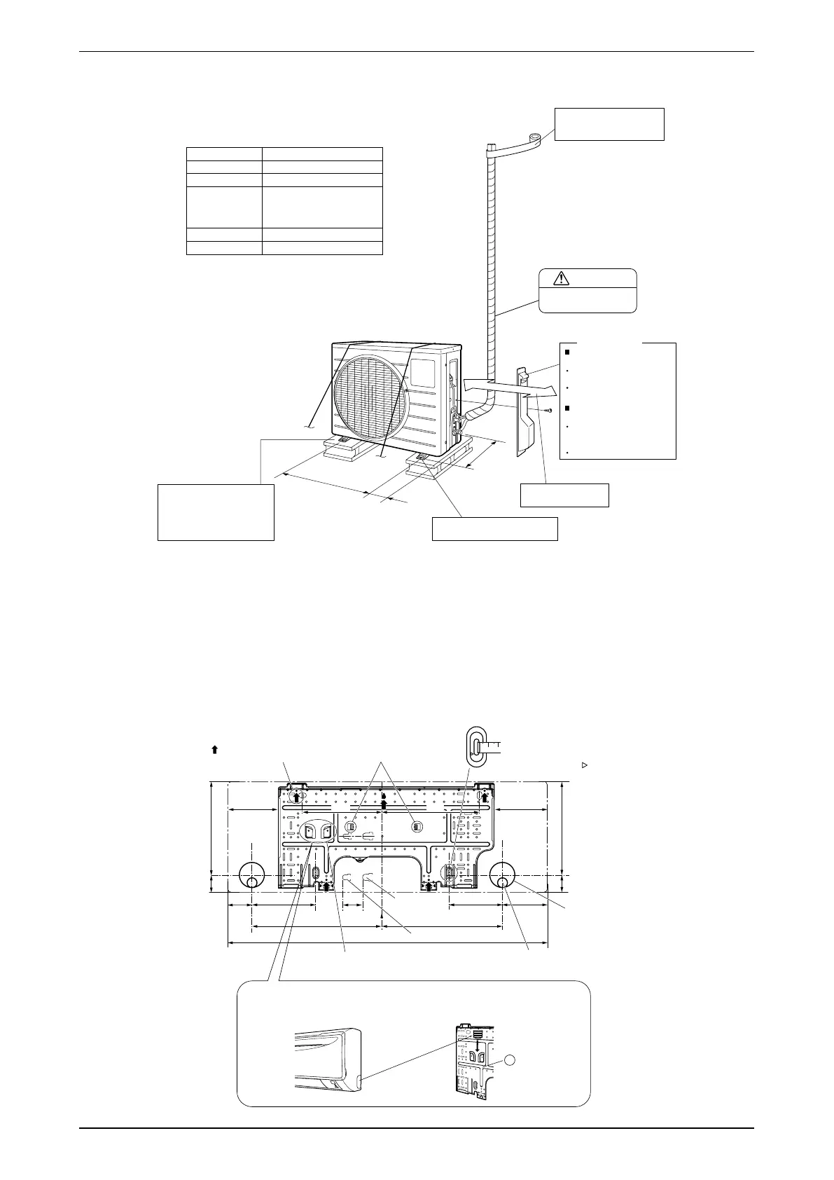
CAUTION
Set the piping length from
1.5m to 15m.
Wrap the insulation pipe with
the finishing tape from bottom
to top.
In sites with poor drainage, use
block bases for outdoor unit.
Adjust foot height until the unit
is leveled. Otherwise, water
leakage or pooling of water may
occur.
Where there is a danger of the unit
falling, use foot bolts, or wires.
Allow space for piping
and electrical servicing.
250mm from wall
unit: mm
O.D. 9.5mm
Gas pipe
Liquid pipe
O.D. 6.4mm
20g/m
Max. allowable length
12m
15m
Max. allowable height
Additional refrigerant
required for refrigerant
pipe exceeding
10m in length.
*
Be sure to add the proper amount of additional refrigerant.
Failure to do so may result in reduced perfomance.
*
The suggested shortest pipe length is 1.5m, in order to avoid
noise from the outdoor unit and vibration.
(Mechanical noise and vibration may occur depending on how
the unit is installed and the environment in which it is used.)
1.5m
Min. allowable length
470
(Foot bolt-hole centres)
(From unit’s side)
96
(Foot bolt-hole
centres)
300
How to remove the stop
valve cover
Remove the screw on the
stop valve cover.
Slide the lid downward
to remove it.
How to attach the stop
valve cover
Insert the upper part of
the stop valve cover into the
outdoor unit to install.
Tighten the screws.
Stop valve cover
*