Hardware Manual
18
The table below shows the DI/DO connection specifications:
TTL - compatible logic levels
Logic level 1: 3.1V ~ 12V
Transistor (Open Collector)
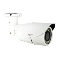
Connecting Audio Devices
Audio input / output devices, such as an active microphone or speaker can be connected to
the camera using the supplied terminal block which is already connected to the AUDIO cable
connector.
Loosen the screw and insert the wire through the pin slot, then tighten the
screw to secure the wire.
To connect audio devices, map the pins to one of the pin combinations
below:
Connect the wires of the audio output device to OUT
and G (Ground).
Connect the wires of the audio input device to IN and
G (Ground).
NOTE: For more information about AUDIO in connections, please refer to the Knowledge
Base article How to Use Audio-in of ACTi Cameras, downloadable from the link below
(http://www.acti.com/support/KnowledgeBase/outside/detail.asp?KB_ID=KB20100114003).