EasyManua.ls Logo

ACTi TCD-2100 - I;O and Network Ports

ACTi TCD-2100
17 pages
Print Icon
To Next Page IconTo Next Page
To Previous Page IconTo Previous Page
Loading...
www.acti.com
TCD-2100 Hardware Users Manual
10
On (3s)
On
1s
Power On
About 20 Seconds
Stay On
Off (about 15s)
Off (10~15s)
Restore to Default
Complete
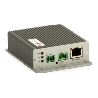
8) Terminal Blocks for Digital Input / Output
The IP device supports one alarm input and one transistor output. Please connect DI with Pin 1
and 3 and connect DO with Pin 2 and 4.
9) Ethernet Port
The IP device connects to the Ethernet via a standard RJ45 connector. Supporting NWAY, this
IP device can auto detect the speed of local network segment (10Base-T/100Base-TX
Ethernet).
PIN
NAME
1
GND
2
DC + 12V
3
Digital Input
4
Transistor Output
DI
Connection design
TTL-compatible logic levels
Voltage
To trigger (low)
Logic level 0: 0V ~ 0.4V
Normal (high)
Logic level 1: 3.1V ~ 30V
Current
10mA ~ 100mA
DO
Connection design
Transistor (Open Drain)
Voltage & Current
Internally powered at 12 V. Limit to no more than
24V DC if connected to external power, <100mA

Other manuals for ACTi TCD-2100

Related product manuals