Encoder Hardware Manual
10
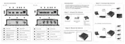
Connects to the serial port of an analog device for
RS-485 / RS-422 communication to control encoder
functions like pan-tilt, zoom, etc. See Connecting a
Serial Device (Optional) on page 23 for more
information.
Used to restore the factory default settings, including
the administrator’s password. Using a pointed object,
such as a pen, press and hold the Reset button for 5
seconds or until the Power LED lights up.
In case the encoder is connected to a non-PoE
(Power over Ethernet) switch, use this connector to
connect the encoder to an external power adaptor.
See Connecting a Power Adapter (Optional) on
page 16 for more information.
Connects to the network using a standard Ethernet
cable.
Insert a memory card (not included) into the slot for
local recording purposes. See How to Install /
Remove the Memory Card on page 25 for more
information.
NOTE: Supports only microSDHC and microSDXC
cards.
Connects to an external monitor for video monitoring
through BNC connection. See Connecting the Video
Output Device (V21 / V22 only) on page 15 for more
information.
NOTE: Video cable with BNC connector not included
in the package.
Connects an analog camera through BNC connection.
See Connecting the Analog Camera on page 15 for
more information.
NOTE: Video cable with BNC connector not included
in the package.