Troubleshooting the Zone – Device Blink Codes
All nLight devices are equipped with status LEDs. These LEDs are used in
conjunction with the device’s push button for programming and conguration,
but the rest of the time they indicate status and display any error code that may
be present at the device. The table below tells how to interpret common error
codes from the LED blinks.
Blink Pattern Meaning
Device has two LEDs, and
the left LED is on solid (not
blinking)
Device is Polling on the network, wait for polling
to nish.
Constant rapid ash of
all LEDs
A software update is in process. Wait for the
update to complete.
Slow, steady blink on all
LEDs
Device is in “bootloader” mode - starting up.
Wait for startup to complete.
Rapid ash for 1 second,
followed by two blinks
No TIA-485 communications between devices.
Check CAT-5e cable connections, pins, etc.
Rapid ash for 1 second,
followed by three blinks
Low voltage on the port; this indicates a lack of
bus power. Add a bus-powering device to supply
additional voltage. See nLight Power Consider-
ations for more info.
Rapid ash for 1 second,
followed by four blinks
The device’s rmware is incompatible with the
other devices in this zone. Typically indicates
an old, outdated device. Remove the device
and replace it with an up-to-date unit, or use
an nCOMM utility kit to update the device’s
rmware to a compatible version.
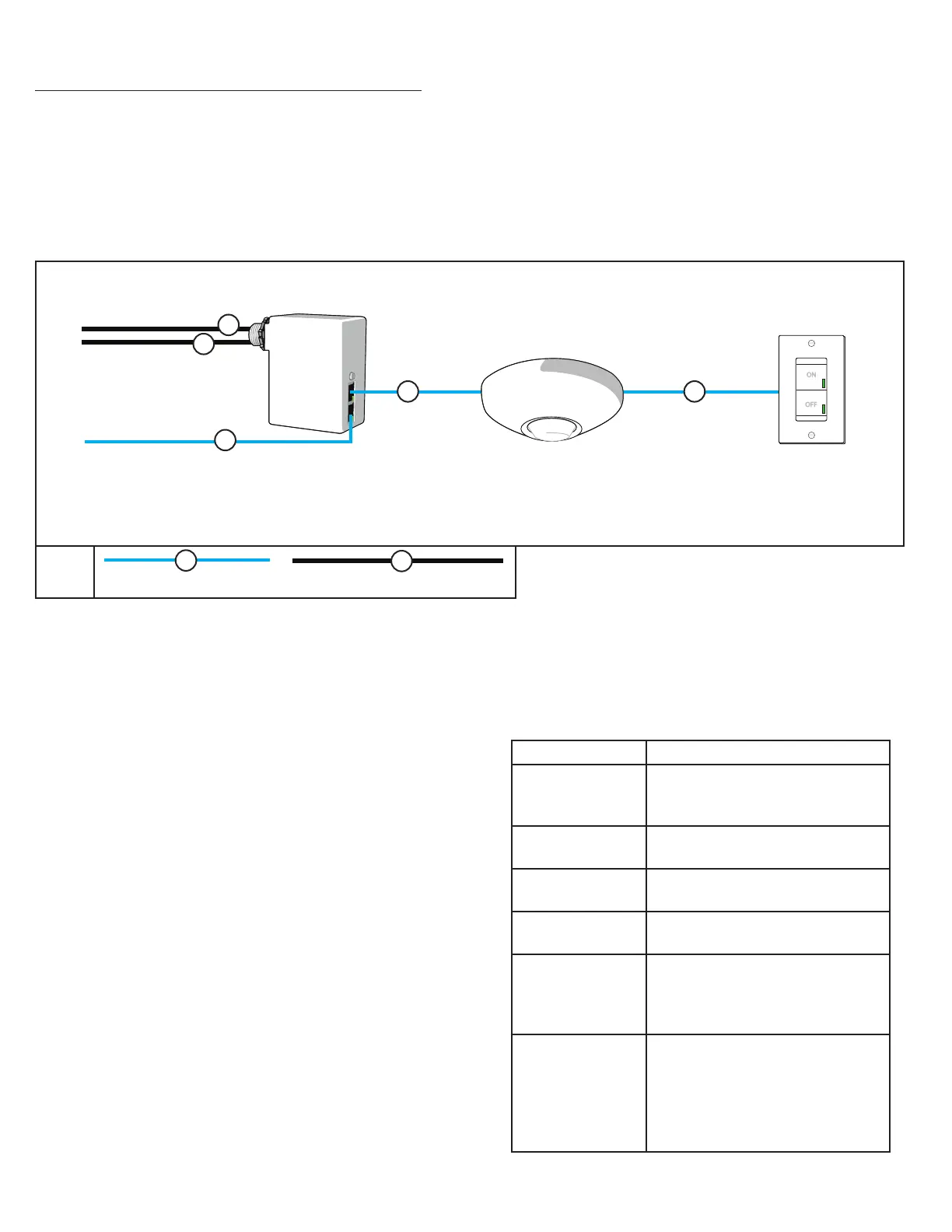
INSTALLING A CONTROL ZONE
nLight devices in zones are wired together in any order, using CAT-5e cables.
Daisy-chain (linear) topology is strongly recommended, however use of splitters is
allowed if the cable run is short. Control zones can have a maximum of 128 nLight
devices wired together in any order on a single bus of CAT-5e cables. The maximum
cable length for a zone is 1500 feet. Typically, one or more of the devices in a zone
will supply sucient bus power for all devices in the zone (see bus power section on
reverse) to power up and begin default operation without any conguration.
to BRIDGE PORT
(optional)
nLIGHT Control Zone - Typical Oce
A
B
485 Bus (CAT-5e) LINE VOLTAGE CLASS 1
KEY
from
DISTRIBUTION
to
LIGHTING LOAD
B
B
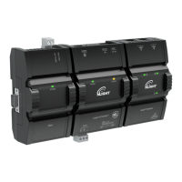
nPP16
Power Pack
contains relay for control of
lighting load & supplies
low voltage power to
other nLight devices
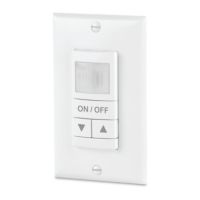
Occupancy Sensor WallPod
A
A A
nCM 9
nPODM
Wiring steps
1. Locate one of the devices that provides power to the bus, and run CAT-5e
cable to the next nLight device in the daisy chain. Install connectors as
necessary, terminating cables according to T568B. Keep in mind the tips in
the Do’s and Don’ts section to help your install go smoothly.
2. If the device location has not previously been recorded, wiring is a good
opportunity to do so. It is very helpful information to have later on. If there
is a second ID# sticker on the device, pull it and use it to record the device
ID#. Adjacent to the sticker, record the device type (i.e. LED xture or ceiling
sensor) and location (i.e. Room 216 Row 2 ceiling)
3. Plug in the CAT-5e cable to the power-supplying device. It does not matter
which of the RJ-45 ports you plug into on a device with two ports.
4. Plug the other end of the CAT-5e cable into an available RJ-45 port at the
next device.
5. As soon as the device is plugged in and has bus power, the LED should
display a rapid ash followed by two blinks as the device boots up. If you
don’t see LEDs come on, re-check the cable, using the tips from the Do’s and
Don’ts table.
6. As each device is added, you’ll see LED activity during network discovery,
after which the LEDs will settle into default states. Power Pack and switch
(WallPOD) LEDs will be either solid on or o; occupancy sensor LEDs light up
according to what they observe. If the LEDs on a device are instead blinking
in a pattern, see the Device Blink Codes table, at right.

 Loading...