Troubleshooting the Backbone
You can see the status of an individual Zone as it is connected to the Bridge by
observing the LED for that Bridge Port, and interpreting its Blink Pattern when in
port status mode.
Port Status
Blink Pattern
Meaning
1 Blink Zone is healthy.
2 Blinks Upstream Bridge or Gateway is detected.
4 Blinks Downstream Bridge is detected.
5 Blinks Too many Adds/Deletes on the port. Reset the Bridge.
6 Blinks Two Bridge ports are cabled together, creating a Bridge
Loop. Check Bridge wiring and remove the loop.
You should also observe the device count at the Gateway, and check that the
count increments correctly as each Control Zone is cabled to its Bridge port.
Checking Device Count from Bridge
The Bridge has a push-button and one indicator LED per port. Pressing the
push-button causes the LEDs to toggle between port status mode and device
count mode, in which each port LED (one after another) reports the number
of detected devices by blinking out a two digit number - 1st DIGIT (pause) 2nd
DIGIT. Rapid blinking indicates the number zero. If the count is greater than
99, three digits will be blinked in a similar manner. A port LED that does not
blink, or blinks erratically, indicates a broken or miswired CAT-5e connection.
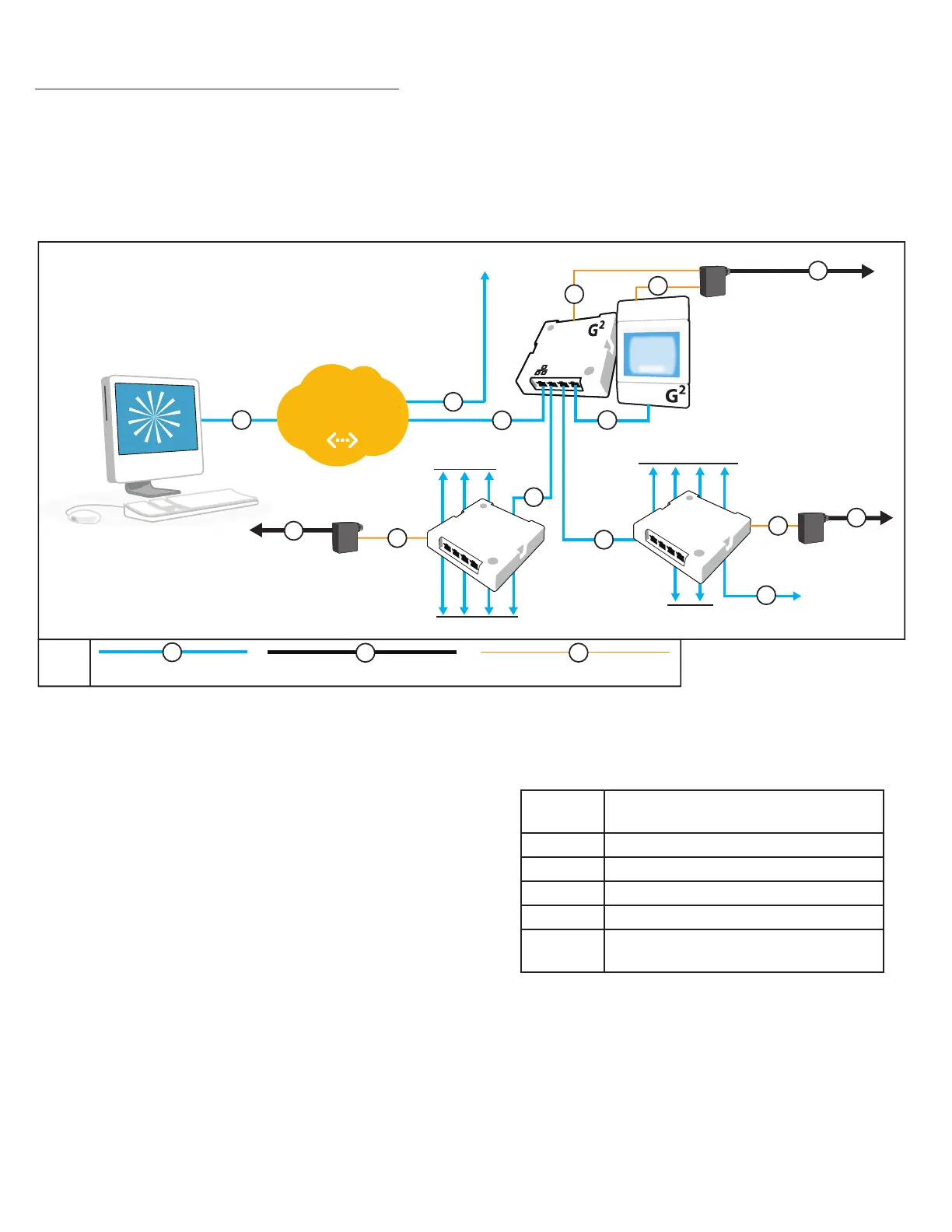
INSTALLING A BACKBONE
An nLight backbone consists of devices called “Bridges” and “Gateways”
connected with CAT-5e cables. Individual control zones are each cabled to a
port on a Bridge, which may also be cabled to other Bridges or directly to a
single Gateway. One or more Gateways are then typically linked together over
an Ethernet LAN/WAN (not provided) to a host computer or server (supplied by
customer) running the SensorView management software.
B
A
A
PS-250 Power Supply
SENSORVIEW
MANAGEMENT
SOFTWARE
A
A
to LIGHTING ZONES
to LIGHTING ZONES
to LIGHTING ZONES
to LIGHTING ZONES
to BRIDGE or
LIGHTING ZONE
C
B
BRIDGE
BRIDGE
PS-150 POWER SUPPLY
LAN
1
2
3
to
additional
GATEWAYS
A
A
A
C
C
B
PS-150 POWER SUPPLY
A
B
485 Bus (CAT-5e) LINE VOLTAGE CLASS 1
KEY
C
LOW VOLTAGE CLASS 2
nLIGHT Backbone - Example Network
nGWY2 GFX
nGWY2
CTRL
C
Wiring Steps
1. Start by installing the Gateway device. Conrm that the controller
(nGWY2 CTRL) and display (nGWY2 GFX) are powered, and that the
display is cabled to Port 3 on the controller. A beating green heart
symbol on the display indicates communication is present between
the devices. Note: no other devices besides the nGWY2 CTRL should be
cabled to the rear of the nGWY2 GFX device.
2. The Gateway’s device count should register one on the display.
3. Plug in the rst Bridge to the Port 1 on the controller. The Gateway
display will show the device count increment by one.
4. Plug in one nLight zone at a time to the Bridge. Check that the
Gateway’s device count increments by the number of devices in
each zone added. If it is not already recorded, write down the Bridge
location, Zone name, and the Bridge port number used. NOTE: If it is not
convenient to get the device count from the Gateway, see “Checking
Device Count from Bridge”, at right.
5. Repeat Step 4 until all zones are connected to the rst Bridge. Note:
additional Bridges may be connected to Bridge ports. For example, a
Bridge may be cabled to 5 downstream control zones, 2 downstream
Bridges, and the upstream Gateway.
6. Repeat Steps 3 - 5 using Port 2 on the Gateway controller if necessary.
 Loading...