8
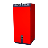
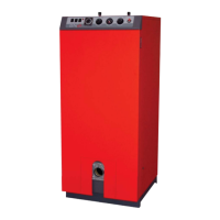
INSTALLATION
ELECTRICAL CONNECTIONS
Principle of supply
The boiler operates on a 230 V/50 Hz single-phase supply. You
should install a control box with main switch and fuses externally to
the boiler to allow the boiler to be isolated from the supply for
servicing and repairs.
Statutory compliance
The installation must comply with your local standards and codes of
practice.
Safety
The stainless steel water tank must be provided with a separate
earth.
The boiler must be isolated from the electrical supply
before any work is carried out on it.
The heater consists of two 2.4 kW electrical resistors.
One of these two resistors is wired and used as the
main resistor. The other resistor is not used, and
serves only as a back-up if the first resistor becomes
faulty.
The two resistors must never be connected to operate
together, as this will damage the internal wiring of the
boiler.
Wiring diagram key
1. Main switch
2. Hot water control thermostat
3. 24-hour programmer
4. Heating control thermostat (60/90°C)
5. Manual reset high limit thermostat (103°C max.)
6. Electrical resistor indicator lamp
7. Energy selection switch
8. Burner
9. Pump
10. Room thermostat
(optional)
11. Summer/Winter switch
B. Blue
Bk. Black
Br. Brown
G. Grey
Or. Orange
Pk. Pink
R. Red
V. Violet
W. White
Y/Gr. Yellow/Green
Schematic diagram of the boiler electrical circuit