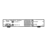
ADA T100S owner’s manual
Power amp last. To shut down your system, turn volume attenuators down and use the
reverse procedure: Power amp first, Preamp last.
NOTE: To prolong tube life, let your T100S warm-up in standby mode for at least one
minute before use. Before turning your T100S off let it cool in standby mode
or at least one minute.
TUBE REPLACEMENT
With proper care the tubes in your T100S will yield many hours of performance. When your
amp becomes microphonic and/or noisy, it's time to replace the tubes. Only ADA
replacement tubes should be used. Tubes must be replaced as a set per channel. To replace
tubes, first disconnect A.C. power. Let your T100S cool with power turned off for one
minute to allow caps to discharge. Remove top cover plate. Using caution not to break
tubes, pull spring-connected tube retainers off the top of the tubes and let them rest against
the side of the tubes. Pull tubes from their sockets and plug in the new ADA tubes. Carefully
pull tube retainers into position. Replace top cover and screws. Note: Tubes are fragile,
handle them with care. To order a matched set of ADA tubes, contact your Authorized ADA
Dealer.
SPEAKER IMPEDANCE
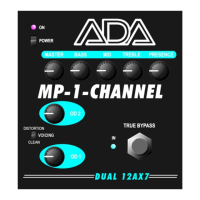
It is important to always "match" your speaker system to your power amplifier, especially
when using component systems such as the ADA MP-1 & T100S power amplifier. A proper
impedance match will give you optimal performance and keep your power amp in a "safe
operating area" so it won't overheat or blow fuses.
To get the proper impedance match using more than one speaker involves a little bit of
thought because the overall impedance of all the speakers on a channel is what the amplifier
"sees". The overall impedance is the important value that must be known for proper
impedance matching.
The impedance of a single speaker is the amount of resistance to an electrical signal at 1000
cycles per second (Kilohertz, abbreviated KHz). A 16 ohm speaker means that there is 16
ohms (units of resistance) at 1KHz. When connecting a single 8 ohm speaker to an amplifier,
the amplifier will be "driving" an 8 ohm load.
When speaker cabinets have more than one speaker in them, and depending on how they
are connected, the impedance can have various values.
In these diagrams we are using the same type of 16 ohm speaker. Diagram A is a simple
one speaker configuration. Diagram B is a series connection. To get the overall impedance
add the two speakers' impedances (16 + 16 = 32).
Diagram C is a parallel configuration. Some of the electrical signal goes to the top speaker
and some goes to the bottom. For the two speakers (of equal impedance) the total
impedance is 1/2 of the value of each speaker (1/2 x 16 = 8).
If you have four equal impedance speakers in parallel as shown in diagram D, the overall
impedance is 1/4 of the value of one speaker (1/4 x 16 = 4).
Diagram E is the same as diagram D except the four speakers are split into two cabinets.
Page: 4 of 6
 Loading...