953.028UK User Manual
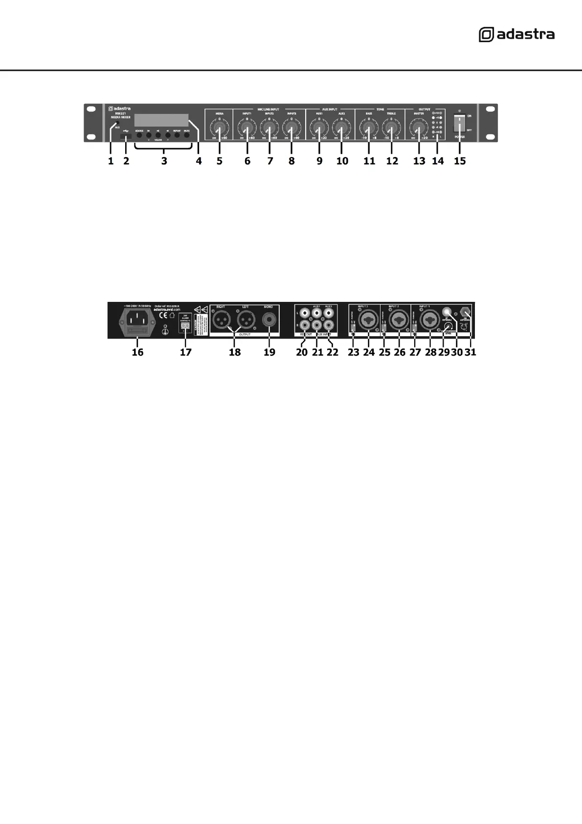
Front panel
Rear panel
Connection
Ensure the Power (15) is switched off until all input and output connections are in place.
Turn all rotary level controls (5 - 10) and Master level (13) fully down (anti-clockwise) to avoid loud noises
when switching on.
Set the BASS and TREBLE Tone controls (11, 12) to the vertical position (zero)
Channels 1, 2 and 3 can accept microphones or mono line level inputs, such as CD, TV or electronic keyboard.
Connect the main microphone or line level signal to Mic/Line 1 input (28) on the rear panel via balanced XLR
or 6.3mm jack.
If a condenser mic is being used, connect via XLR, select Mic level and 20V Phantom power on via the channel
1 DIP switches (27)
Further mic or line level signals can be connected to inputs 2 and 3 (24, 26) in the same way as for channel 1
Set the DIP switches for channels 2 and 3 (23, 25) to suit the input source.
Connect stereo line level sources to AUX 1 and AUX 2 RCA inputs (21, 22).
Outputs are available on L+R balanced XLR (18) for stereo operation and a single 6.3mm unbalanced jack
(19) summed to mono. Record outputs on L+R RCA (20) are unaffected by the Master level control.
3.5mm AUX input to media player
Aux line input 1 level control
Aux line input 2 level control
Media player control panel
Bass EQ boost/cut control
Treble EQ boost/cut control
Media player level control
Master output level control
Mic/Line input 1 level control
Output level LED indicators
Mic/Line input 2 level control
Power switch and indicator
Mic/Line input 3 level control
IEC mains inlet and fuse holder
Input 3 balanced XLR/jack
24V emergency alarm contacts
Mic/Line and phantom switches Input 2
Input 2 balanced XLR/jack
6.3mm jack mono unbalanced output
Mic/Line and phantom switches Input 1
Input 1 balanced XLR/jack
Mic/Line and phantom switches Input 3
FM tuner antenna F connector