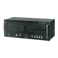
SOUND SHAPER THREE CIRCUIT DESCRIPTION
MAIN POWER SUPPLY (Refer to Figure A)
Power Transformer T 1001 provides three tapped secondary windings.
One delivers +26.4 V /- 26.0 V DC at +104/-137 rnA (no
i
all fro
capacitor circuit consisting of a bridge rectifier D701 and C7
3,
C7
4.
The second delivers -25.2 VDC at -1.1 rnA (nominal)
fro a
circuit consisting of rectifier D709 and C715. This voltage supplies - e
TR201.
The third delivers 60 VDC at 87.5 mA (nominal) from full-wave
rectifi
ing of rectifiers D702, D703 and C704.
The voltage which is rectified by D701 provides both bases of TR703
c T
andR717.
TR703/TR705 and TR704/TR706 consist of voltage-regulator circuits 'or
voltages.
These regulator circuits provide approx. +15.4 V /-15 V DC to LED Meter ana 5"
Control circuit which are constant and independent of the load current.
The reference voltage of this circuit is obtained from Zener Diode D708. The base voltage of T
is supplied from the voltage divider R708 and R709.
TR703 turn-on is determined by comparing the output voltage to the reference voltage and is
controlled by changes in collector current of TR705.
Voltage, which is rectified from D702 and D703, divider network R702 and R705 provides approx.
50 VDC. This is filtered further by C703, R704 and fed to the base of divider transistor TR701
which is connected to TR702 in a Darlington emitter-follower configuration. The reference voltage
of this circuit is obtained from Zener Diodes D704 and D705 (Approx. 44 VDC).
The emitter of TR702, decoupled by C701, provides approx. 41.5 VDC to the Equalizer and Meter
circuits. The collectors TR701 and TR702 are returned to 57.4 VDC through R701 which limits the
transistor collector circuits.
The Darlington connection of TR701 and TR702 provides a low output impedance. The base of
TR701 presents negligible loading on the voltage divider network, hence the ripple voltage at
TR702 emitter is small. Except for the small base current into TR701, the full load current flows
through R701.
a full-wave bridge rectifier -
- CI
e roc"ifier - cspactitor
cireui , e base of
co
Figure A
- 4 -
 Loading...