5
4
3. PACKAGE CONTENTS
Contents dependent on model type:
• Diallerboardinplastichousing
• Ethernetcable(IRIS-4220&240)
• 2/3/4Gantenna(IRIS-4200&240)
• Stylusfortouchscreennavigation
• 18kΩsenseresistorfordialcapturetamperdetection
4. BOARD
CONFIGURATION
LED COLOUR INDICATION
Yellow flashing Not currently configured or indicating that there are some current faults outstanding.
Yellow constant Communicating and no current faults (flickers on every poll).
5. BEFORE YOU START
Monitoring Centre (ARC)
Make sure that the monitoring centre to which the IRIS-4 2 Series device will send alarm signals is equipped
with the appropriate IRIS Secure Apps receiving system. The following information should be obtained from
the Monitoring Centre.
Dialler account number:
Monitoring centre IP address:
Ethernet Connection Details
The customer’s Ethernet (LAN) network details are required in order to connect the IRIS-4 220 & 240.
Obtain the following information from the customer.
Fixed IP address or DHCP:
Fixed DHCP
If using DHCP then the following information will not be required
as it will be assigned by the network.
IP address:
Gateway address:
Subnet mask address:
2/3/4G SIM Card and Access Point Name
If the installation uses 2/3/4G then a SIM card will be required. The IRIS-4 240 will also need to be given a
2/3/4G ‘Access Point Name’ (APN) and other possible configurations as shown below. Obtain these from the
SIM card provider.
Access Point Name (APN):
User name (USR):
Password (PWD):
SIM Pin:
4
1
3
2
5
6
7
8
9
12
13
11
10
14
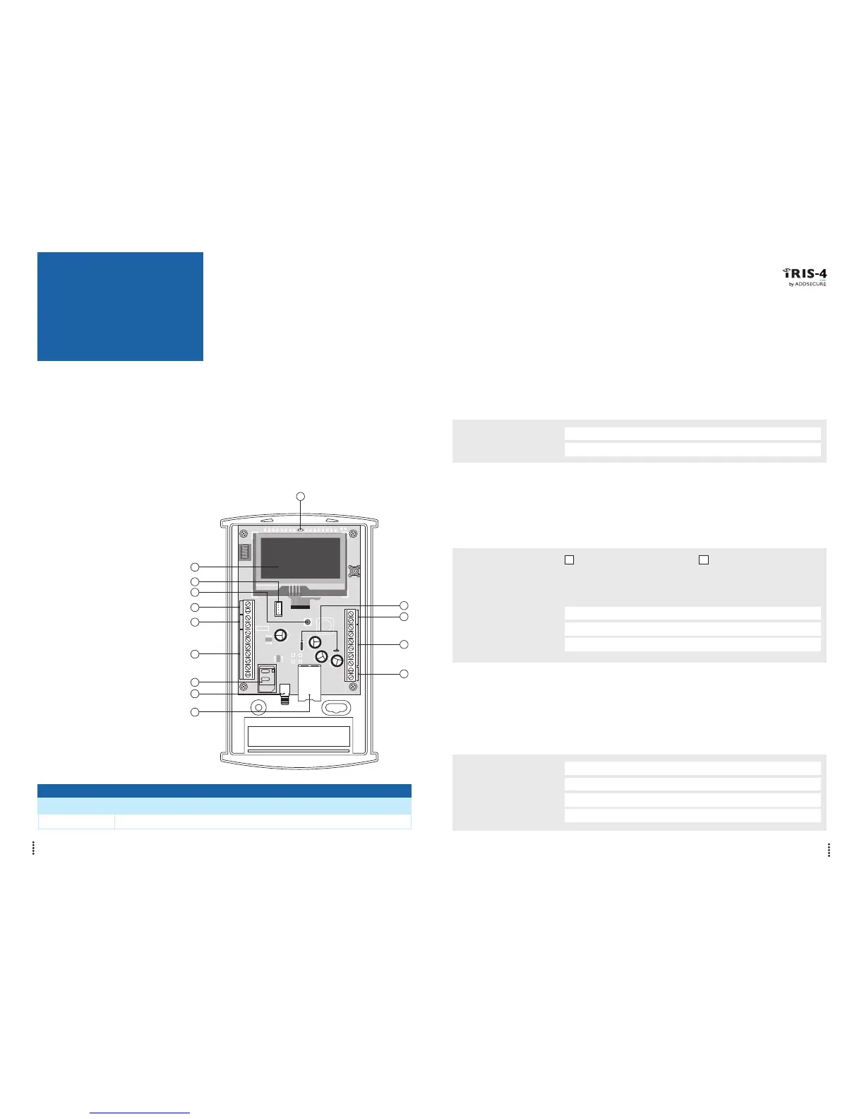
① = Touch screen
② = Serial (TTL)
③ = Front tamper
④ = Dial capture port
and screw terminals
⑤ = RS485
⑥ = Pin inputs
⑦ = SIM card holder
⑧ = 2/3/4G antenna
⑨ = Ethernet
⑩ = DC power
⑪ = Relays
⑫ = RS232
⑬ = Micro USB
⑭ = SYS LED