7
6
Use the following procedure to install the
IRIS-4 2 Series dialler:
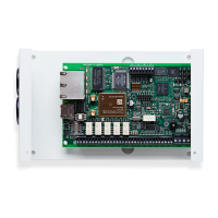
6.1. Mounting
Choose a suitable location, taking into consideration
the routing of cables: power and panel dialler inter-
face. Remove the two case fixing screws under the
slide cover and open the unit, remove the two PCB
fixing screws and remove the PCB.
Position the housing on the wall and drill three
holes. Feed the cables through the opening at the
base of the plate, or via the ‘knockouts’, and secure
the plate to the wall with the three screws supplied.
6.2. Power
The IRIS-4 2 Series dialler can be powered using a
separate or Aux 9-28V DC power supply specified to
deliver a minimum 1A current using the screw termi-
nals indicated in Section 4 “Board Configuration”.
Note:
For Radio Equipment Directive compliance, the
power cable must be no longer than 3 meters in
length.
Fit the power cable. DO NOT APPLY POWER TO
THE DIALLER UNTIL INDICATED.
RS485 CONNECTIONS (HONEYWELL GALAXY OR RISCO PROSYS)
IRIS-4 2 Series to Honeywell Galaxy panels
IRIS RS485 Screw terminal To Galaxy Data Bus terminal
0V (Power)
← →
Galaxy (-)
VIN (Power)
← →
Galaxy (+)
A
← →
Galaxy (A)
B
← →
Galaxy (B)
IRIS-4 2 Series to Risco ProSys panels
IRIS RS485 screw terminals To Risco Bus1 terminal
0V (Power)
← →
COM
VIN (Power)
← →
AUX
A
← →
YEL
B
← →
GRN
6. INSTALLING THE IRIS-4 2 SERIES DIALLER
6.3. Connections
Connect cables to the PCB for the system as shown
in Section 4 “Board Configuration”.
• Ethernetenabledsystems(IRIS-4220&240):
Connect the ‘ETH’ connector using the Ethernet
cable to the local IP router/switch or socket that
has been allocated for the LAN/WAN network
IP connection.
• 2/3/4Genabledsystems(IRIS-4 200 & 240):
Fit the supplied T-bar 2/3/4G antenna to the
‘Cell Ant’ connector but do not fix in place
until after performing the 2/3/4G network scan.
• Dialcaptureport(optionalandformoreinfor-
mation see section below).
• 4xPinInputs(optionalandformoreinforma-
tion see section below).
Optional serial connection
The following three connections are optional and
depend on the panel connection method. By default,
the IRIS-4 2 Series RS485 connection is for Honey-
well Galaxy panels.
Note: For alternative panel manufacturers’ selection,
use the touch screen Installers menu – settings to select
the option required. Please contact AddSecure for
further details or download the full panel installation
manual available from http://www.addsecure.com.
• RS485currentlyavailableforHoneywellGalaxy
data bus (Alarms and Upload/download) or
Risco ProSys bus (Upload/download) connec-
tions (optional).
• SerialTTL(optional).
• RS232screwterminal(optional).
For more details on the cable requirements/connec-
tions please see details on next page.
6.4. 2/3/4G SIM card (IRIS-4 200 & 240)
DO NOT FIT SIM card until after you have
performed the 2/3/4G Network Scan detailed
in the Section 6.8 “Configuration”. You will be
prompted when to insert the SIM card.
6.5. Dial Capture
Dial Capture enabled systems: Connect the two dial
screw terminals to the alarm panel dialler telecoms
line connection.
Note: Polarity is not important in this instance.
For EN50136-2: 2013 compliance fit the supplied
18kΩsenseresistorinparallelwiththedialleroutput
of the alarm panel, at the alarm panel end of the
cable.
Note:
This resistor enables the dialler to detect cable faults
and/or tampers, the Monitoring Centre will also
need to enable the dial port monitoring on the IRIS
Secure Apps software to receive alarm notifications.