Do you have a question about the AddSecure Edge RT7020 Enterprise and is the answer not in the manual?
Installation manual for Edge RT7020 Enterprise.
Details on the 8 digital inputs for alarm activation and supervised mode.
How the device receives and decodes SIA alarms from an analog dialer.
Process for transmitting alarms via the customer's network using IP.
Procedure for handling and delivering dialed alarms, including fault notification.
Connecting fire alarm and fault outputs from the fire panel to Edge RT7020 inputs.
Connecting Edge RT7020 outputs (REL1, REL4, REL5) to fire panel inputs.
Pre-installation checks for IP communication and network access.
Detailed steps to create and apply configuration files via Edge Manager.
Process for verifying functionality and completing the device setup.
How to perform a status check of the unit via Edge Manager.
Procedure for replacing the PCB and re-activating the terminal.
Steps to perform a factory reset on the Edge RT7020 Enterprise.
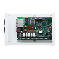
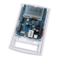
Detailed description of all physical connections and terminal functions.
Functionality and settings for the eight DIP switches on the unit.
Explanation of the meaning of various LED states and patterns.
Details on power requirements, operational current, and ambient temperature range.
Lists relevant certifications and standards for intrusion and fire alarm transmission.
The Edge RT7020 Enterprise is a versatile communication device primarily designed for secure alarm transmission in fire and intrusion detection systems. It functions as an external dialer and/or an IP-converter, offering robust communication pathways over both fixed-line Ethernet (primary) and cellular networks (2G, 3G, or 4G) as a secondary option. This dual-path capability ensures reliable alarm delivery even if one communication method fails. Beyond alarm transmission, the Edge RT7020 can also be configured to provide remote access to connected devices, utilizing either Ethernet or cellular networks.
One of the core usage features of the Edge RT7020 Enterprise is its array of 8 digital inputs. These inputs are highly configurable and can be used to connect various external alarm devices or relay outputs from a fire alarm panel. Each input can be set up with specific event codes during system configuration, allowing for precise identification of the alarm source. The inputs are activated by either a potential-free closing or opening to the system ground plane, depending on the configuration. A significant advantage is the support for supervised mode on all inputs, which enables the detection of tamper conditions (infinite or no resistance) and the delivery of individual tamper messages to the alarm receiving center.
Another key feature is the integrated dialer capture input, which simulates an analog telephone line. This allows the Edge RT7020 to receive alarms from intrusion or fire panels that communicate using the SIA protocol. Upon receiving a dialed number from the panel, the Edge RT7020 delivers a start tone back to the dialer. The dialer then transmits its alarm message, which the Edge RT7020 decodes, converts, and delivers via TCP/IP to a designated alarm receiving center. Alarm transmission can be triggered by several events: activation of any of the digital inputs, activation of internal error controls (such as Ethernet or cellular errors), activation of an alarm via the dial capture interface, or activation of an alarm through the RS232 or RS485 serial interfaces.
For alarms transmitted over IP, the Edge RT7020 connects to the local area network (LAN) using a standard network cable. It then sends alarms over the customer's network via the internet to the alarm receiving center. Due to its very low data rates, the Edge RT7020 typically has minimal impact on other network traffic. For fixed internet connectivity, specific parameters like IP address, default gateway, and net mask must be configured. Alternatively, DHCP can be activated, allowing the terminal to automatically obtain these IP parameters when connected to the LAN. It's crucial that the customer's firewall is configured to allow outbound traffic, specifically opening the port numbers used by the Connect platform. If these ports are not opened, the Edge RT7020 will automatically switch to using the radio path, though fixed Ethernet offers advantages in speed and reduced data traffic. For 2G/3G/4G communication, no additional settings are required for the radio interface to function.
Special considerations apply when connecting the Edge RT7020 Enterprise to a fire panel. For instance, the output for a fire alarm from the fire panel (CIE) should be connected to input 1 on the Edge RT7020, and the fault output from the CIE to input 2. If the Edge RT7020 is installed in its own enclosure, separate from the fire panel, inputs 1 and 2 must be supervised to detect tamper conditions (open and short circuits). This supervision is enabled by connecting the lines via two 4k7 resistors. Additionally, outputs REL1, REL4, and REL5 from the Edge RT7020 can be connected to inputs on the fire panel. If the Edge RT7020 is in its own enclosure, it must be powered by a source certified according to EN54-4, such as directly from the fire panel.
The device provides clear indications of alarm transmission status. When transmission starts, LED2 (for Ethernet) or LED3 (for radio) blinks rapidly. A positive acknowledgment from the receiver is indicated by both LED2 and LED3 blinking three times at a slower frequency, while a negative acknowledgment is shown by LED4 (red) blinking three times. A successful transmission also closes REL5 for 2 seconds, while an unsuccessful or absent acknowledgment closes REL4 for 2 seconds. System failures, such as a total loss of communication or tamper on an input, are indicated by REL1 being held open. Regular testing is recommended, at least once a year, by activating input 1 for fire alarm transmission tests and input 2 for fault transmission tests. Internal fault states can be tested by applying appropriate conditions, such as removing the Ethernet cable to test for an Ethernet error alarm.
Programming and commissioning of the Edge RT7020 Enterprise are streamlined through the web portal Edge Manager. All programming files are created in this portal, and the device can be programmed and commissioned directly from there. Before installation, a checklist ensures that the Edge RT7020 has internet access, either via radio, fixed Ethernet, or both. If connecting to a customer's local network, IT department coordination is necessary to obtain IP parameters or confirm DHCP support. Crucially, the customer's firewall must allow outbound traffic on specific ports for the Connect platform and Edge Manager portal.
The programming process involves creating the configuration file in Edge Manager, powering up the unit until LEDs indicate "Ready for programming," logging into Edge Manager, selecting the desired configuration file, and clicking "Program." If it's a new unit, the Activation Code from the label is entered, and the unit automatically downloads and stores the configuration. "Programming completed" is indicated in the portal. Commissioning follows by clicking "Commission," which connects the unit to the Connect platform, verifies functionality, and indicates "Commissioning completed" in the portal. Once commissioned, the alarm transmission part of the Edge RT7020 is ready for use. A status check can be performed at any time from Edge Manager while the unit is in operation.
Maintenance features include the ability to handle PCB changes and perform a factory reset. If a PCB is exchanged, a new activation of the terminal with the Connect platform and the Alarm Receiving Centre is required, necessitating contact with AddSecure and the ARC. The replacement PCB must be of the same type and model, with all connections and DIP settings replicated from the old unit. After powering up and waiting for "Ready for programming," the correct configuration file is selected in Edge Manager, "New hardware" is clicked, then "Program" with the Activation Code, and finally "Commission."
To perform a factory reset, the power must be disconnected, DIP3 set to the ON position, and power reconnected. The blue LED will start blinking, indicating the reset. It's important to return DIP3 to the OFF position afterward to prevent repeated factory resets on subsequent power cycles. After the reset, the unit needs to be reconfigured by logging into Edge Manager, choosing the correct configuration, clicking "New hardware," then "Program" (entering the Activation Code if needed), and finally "Commission."
The Edge RT7020 features eight DIP switches, each with specific functionality when in the "ON" position. DIP3, for instance, is used for the factory reset during power-up. DIP4 enables the LEDs to show the signal strength of the cellular network. DIP8 blocks all remote access to the terminal, including programming. LED indications provide visual feedback on the device's status. LED1 (blue) indicates the radio module's state: turned off means shut down, blinking once per second means searching for a cellular network, and short blinks every 3rd second means connected to a cellular network. LEDs 2-3 (green) and 4-5 (red) indicate communication and alarm transmission status: blinking patterns differentiate between communication to Edge Manager via Ethernet or cellular, alarm transmission via Ethernet or cellular, successful or unsuccessful transmission, and connection errors to the ARC or local/cellular networks. These detailed LED indications are crucial for troubleshooting and monitoring the device's operational status.
| Manufacturer | AddSecure |
|---|---|
| GPS | Yes |
| Model | RT7020 Enterprise |
| Cellular | Yes |
| Ethernet Ports | 2 |
| Wi-Fi | Yes |
| Certifications | CE |