10
Please note that the screw terminals are specified for AWG 16-30 which
means that cables of 0,5-0,75mm shall be used. Please also note that all
connected cables to the Edge RT7020 shall be secured in such a way that
they are prevented from coming loose or have the cable isolation damaged.
In case cables are inserted into the enclosure via the membrane, holes in
the membrane shall be done using an awl and not by knife. So that the
membrane closes tight around the cable.
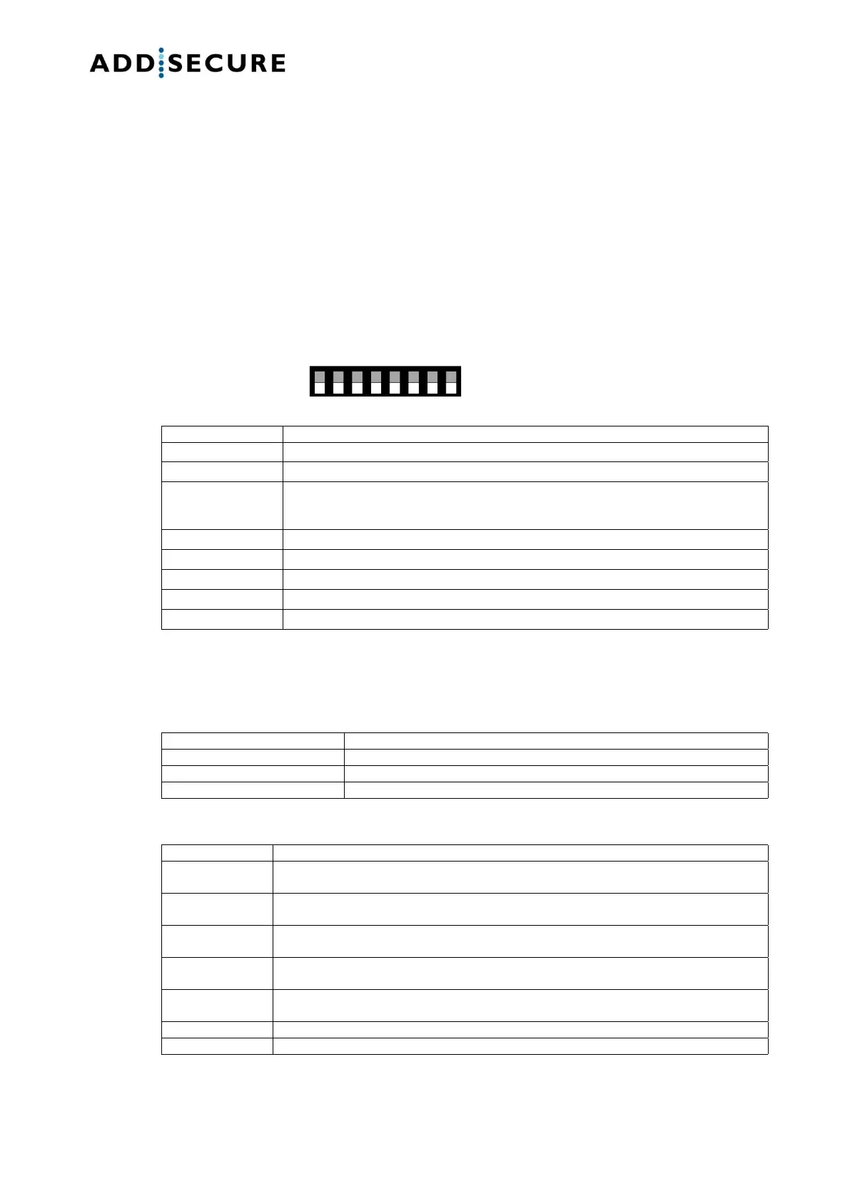
8.2 DIP Switches
The Edge RT7020 has got eight DIP switches with the below functionality
when the DIP switch is in the “ON” position:
ON during restart: Factory reset. If DIP is set to ON during power-up the unit will be
restored to factory default and hence all previous configuration will be erased.
IMPORTANT: DIP is reset to OFF after the blue LED has started to blink.
ON: Signal strength of the cellular network is shown by the LEDs
ON: All remote access to the terminal is blocked, including programming.
8.3 LED indications
8.3.1 LED 1 (blue)
Searching cellular network
Short blinks every 3rd second
Connected to cellular network
8.3.2 LED 2-3 (green) and 4-5 (red)
Blink 1 time/sec: Communication to Edge Manager via Ethernet
Blink 5 times/sec: Alarm transmission via Ethernet
Blink 1 time/sec: Communication to Edge Manager via cellular network
Blink 5 times/sec: Alarm transmission via cellular network
Blinking 3 times together after transmission: Transmission OK
Blinking 1 time/sec: No contact to ARC via Ethernet
Constantly on: Connection error to local network, check the cable
Blinking 1 time/sec: No contact to ARC via cellular network
Constantly on: Connection error to cellular network, for instance no coverage or wrong APN
Indicates signal strength for the cellular network when DIP4 is in ON position
Blinking 3 times together after transmission: Transmission not OK.