-
.
VECTOR
CONTROL
--
4190 4196
0
c
,
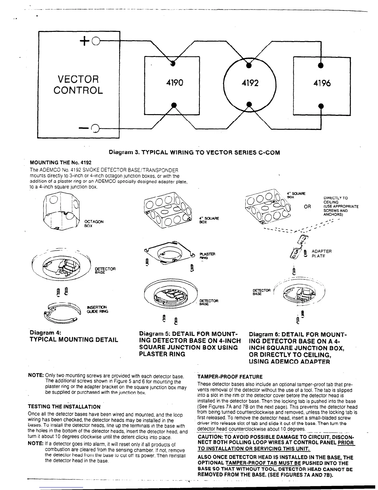
Diagram 3. TYPICAL WIRING TO VECTOR SERIES C-COM
MOUNTING THE No. 4192
The ADEMCO No. 4192 SMOKE DETECTOR BASE!TRANSPONDER
mounts directly to 3-inch or 4-tnch octagon lunctron boxes, or with the
addition of a plaster ring or an ADEMCO specrally designed adapter plate,
to a 4-inch square lundron box
OCTAGON
BOX
Diagram 4:
TYPICAL MOUNTING DETAIL
_ --_
,.,‘..
.;------;
‘,\\
LEFToR
t’
i
DEECTOA
/
BASE
Diagram 5: DETAIL FOR MOUNT-
Diagram 6: DETAIL FOR MOUNT-
ING DETECTOR BASE ON 4-INCH ING DETECTOR BASE ON A 4-
SQUARE JUNCTION BOX USING
PLASTER RING
INCH SQUARE JUNCTION BOX,
OR DIRECTLY TO CEILING,
USING ADEMCO ADAPTER
NOTE: Only two mounting screws are provided with each detector base.
The additional screws shown in Figure 5 and 6 for mounting the
plaster ring or the adapter bracket on the square junction box may
be supplied or purchased with the junction box.
TESTING THE lh%TALLATlON
Once all the detector bases have been wired and mounted, and the
wiring has been checked, the detector heads may be installed in the
loop
bases. To install the detector heads, line up the terminals in the base with
the holes in the bottom of the detector heads, insert the detector head, and
turn it about 10 degrees clockwise until the detent clicks into place.
NOTE: If a detector goes into alarm, it will reset only if all products of
combustion are cleared from the senstng chamber. If not. remove
the detector head from the base to cut off its power. Then reinstall
the detector head in the base.
TAMPER-PROOF FEATURE
These detector bases also include an optional tamper-proof tab that pre-
vents removal of the detector without the use of a tool. The tab is slipped
into a slot in the rim of the detector cover before the detector head is
installed in the detector base. Then the locking tab is pushed into the base
(See Frgures 7A and 78 on the next page). This prevents the detector head
from being turned counterclockwise and removed, unless the locking tab is
first released. To remove the detector head, insert a small-bladed screw
driver into release slot of tab and slide it out of the base. Then turn the
detector head counterclockwise about 10 degrees.
-__^--.. -..- -_.
CAUTION: TO AVOID POSSIBLE DAMAGE To clRculT, DISCON- -
NECT BOTH POLLING LOOP WIRES AT CONTROL PANEL PRIOR
TO INSTALLATION OR SERVICING THIS UNIT.
ALSO ONCE DETECTOR HEAD IS INSTALLED IN THE BASE, THE
OPTIONAL TAMPER-PROOF TAB MUST BE PUSHED INTO THE
BASE SO THAT WITHOUT TOOL, DETECTOR HEAD CANNOT BE
REMOVED FROM THE BASE. (SEE FIGURES 7A AND 78).
. -. _
 Loading...