s:
MARGIN LINES INDICATE PRINCIPAL CHANGES IN THIS l/88 ISSUE *
GENERAL INFORMATION:
WIRING THE No. 4192
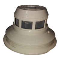
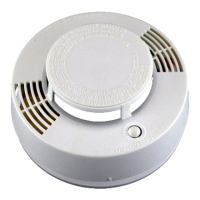
The ADEMCO No. 4192 PLUG-IN SMOKE DETECTOR BASE is a
VECTOR POINT PROTECTION SECURITY SYSTEM component. It IS
intended for use with interchangeable UL Ltsted detector heads, Model
BK-2851 B (PHOTOELECTRIC); Model BK-2851 BTH (PHOTOELECTRIC
WITH BUILT-IN THERMOSTAT) and Model BK-1851 B (IONIZATION). The
base can be installed on a standard ceiling mount electrical box and both
the base and the detector are powered through the polling loop.
IMPORTANT! The instructions which accompany the aforementtoned
detector heads only parttally pertatn to the No. 4192 SMOKE DETECTOR
BASE/TRANSPONDER. The relevant sections are: Preface; Specifica-
tions; SENSITIVITY TESTING AND MAINTENANCE, TAMPER-
PROOF FEATURE, and LIMITATIONS OF SMOKE DETECTORS.
All wrring must be installed in compliance wrth the National Electrical Code
and with all local codes. For complete lnformatton regardrng the polltng
loop, refer to the instructions which accompany the control panel.
The followmg diagram illustrates the polarzed polling loop jwrrrng terminals
and the ID number programming switch.
OPERATION:
The ADEMCO No. 4192 DETECTOR BASE/TRANSPONDER communi-
cates with the control by a stngle multiplex communrcation crrcutt (the pol-
ling loop). Security is maintained by the control which polls each trans-
ponder on the loop and each transponder responds wtth the status of Its
protection point. The base/transponder uses any one of three rnterchange-
able detector heads to detect combustton.
NOTE: The detector head LED is not used and will not function when
used In contunction with the No. 4192.
INSTALLATION:
WHERE TO INSTALL
For information regarding findtng a suitable location for the detector head
and its base/transponder, refer to the BRK manual 156-210, Appltcatron
Manual for System Combustton Detectors (Available at no charge from
BRK Electrontcs, System Sensor Dtvisron, 780 McClure Road, Aurora, IL
60504-2495).
PREPARING THE No. 4192
Before installing the No. 4192. it must be assigned an identification number
by arranging the DIP switches on the base. Assign the number (allocated
in the control’s system programming worksheet) accordtng to the followtng
chart
.-
1 2345678
pm
OFF OFF OFF OFF
OFF OFF OFF OFF
OFF OFF OFF OFF
OFF OFF OFF OFF
OFF OFF OFF OFF
1) OFF OFF OFF OFF
OFF OFF OFF OFF
OFF OFF OFF OFF
OFF OFF. OFF OFF
OFF OFF OF: OFF
OFF OFF OFF OFF
OFF OFF OFF OFF
OFF OFF OFF OFF
OFF OFF OFF OFF
OFF OFF OFF OFF
OFF OFF OFF ON
OFF OFF OFF ON
OFF OFF
-
II
FF
OFF
OFF
OFF
OFF
OFF
“0:
:I
%
%
OFF
OFF
OFF
ON
ON
OFF
OFF
i%
i%
OFF
OFF
ml
OFF ON = 1
ON OFF = 2
ON ON = 3
OFF OFF = 4
OFF ON = 5
g; :‘N’:;
OFF OFF = 6
OFF ON = 9
ON OFF = 10
ON ON = 11
OFF OFF = 12
OFF ON = 13
ON OFF=14
ON ON = 15
OFF OFF = 16
OFF ON = 17
OFF = 16
ON = 1S
g’N’ : ;y
OFF = 22
:F”F : ;;
ON = 25
OFF OFF OFF ON ON OFF ON OFF = 26
OFF OFF OFF ON ON OFF ON ON = 27
OFF OFF OFF ON ON ON OFF OFF = 26
OFF OFF OFF ON ON ON OFF ON = 29
OFF OFF OFF ON ON ON ON OFF = 30
OFF OFF OFF ON ON ON ON ON = 31
OFF OFF ON OFF OFF OFF OFF OFF = 32
OFF OFF ON OFF OFF OFF OFF ON = 33
OFF OFF ON OFF OFF OFF ON OFF = 34
OFF OFF ON OFF OFF OFF ON ON = 35
OFF OFF ON OFF OFF ON OFF OFF = 36
OFF OFF ON OFF OFF ON OFF ON = 37
Diagram 1. TERMINALS AND ID SWITCH
NOTE: Two wires may be used under the same clamping plate. but the
wire run must be broken at the termtnal to matntarn electrical
supervision.
CORRECT
INCORRECT INCORRECT
INSTALLATION
Diagram 2. CORRECT WIRING TECHNIQUE
When wiring the polling loop, observe the following gauge/length
restrictions:
GAUGE LENGTH (ft)’
;i
. . . . . . . . . . . . . . . . . . . . . . 650 (200m)
. . . . . . . . . . . . . . . . . . . .950 (290m)
18 ::. . . . . . . . . . . . . . . . . . . .1500 (460m)
16 . . . . . . . . . . . . . . . . . . . . . .2400 (730m)
‘If multiple wire runs are extended from the control, the maximum total
length of wire that can be connected to the polling loop is 4,000 feet
(1220m). independent of wire gauge. If shrelded wtre is used, the maxi-
mum lengths in the table are not affected except for 16 gauge wire and
the maximum total length of wtre that can be connected to the polling
loop. Those two numbers are now 2000 feet (61 Om). See typical wiring
diagram 3 and also see typical mounting diagrams 4. 5 and 6.
Note that SMOKE DETECTOR BASE/TRANSPONDER can and should be
installed on the same polling loop as burglary transponders.
---.- ..___ -.-..-. ~_._.~
~..