– 2 – – 3 –
INSTALLATION PROCEDURE
Release the detector's mounting bracket by pressing the tab marked PRESS in
the detector's base (see Fig.1 for location of the tab). Note the manner in which
the bracket was attached to the detector base, then put the mounting bracket
aside temporarily. The mounting bracket also serves as the battery compartment
cover.
Battery Installation
1. The detector's battery compartment cover/mounting bracket should have been
removed, as previously indicated. See Figure 2.
2. Install two fresh Duracell MN 1604, 9-volt alkaline batteries in their correct
positions in the detector's battery compartment. Be sure to observe correct
polarity, and do not force the batteries into the compartment. The detector's
LED indicator should flash once every 7 seconds, indicating normal operation.
If the batteries are not installed correctly, the smoke detector will not function.
If the unit appears not to be sending a signal during any of the tests that
follow, check for correct battery installation.
IF BATTERIES ARE REMOVED AND RE-INSERTED FOR ANY REASON.
Before re-inserting the batteries, momentarily bridge the smoke detector's
battery contacts with a metal tool, or wait 90 seconds.
–+
–+
9 VOLT ALKALINE
BATTERY
INSERT SCREWDRIVER
IN HERE AND TWIST
TO RELEASE COVER
9 VOLT ALKALINE
BATTERY
Figure 2. Bottom View of Smoke Detector (mounting bracket removed)
Note: If the detector’s ID has not been programmed into the system (i.e., this is
an initial detector installation), refer to the
PROGRAMMING
section below and
perform the ID “enrolling” procedure before mounting or testing the detector.
Programming
The QED control system must “enroll” the smoke detector’s ID during installation
of the system. Program the 5807 as an “RF” type unit (i.e., supervised RF), and
its loop number as "1."
When prompted for the serial number, either enter it manually, or transmit from
the unit (press the test switch, short the contacts, etc.) To gain access to the
special shorting contacts provided for programming purposes, insert the blade of
a small screwdriver into the opening in the detector base (see Fig. 2 for location)
and twist. This will release the main cover which will then swing away, providing
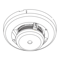
access to the interior of the detector, as shown in Figure 3. With the QED control
in the programming mode, short the two contacts in the detector (shown in Figure
3) with a small screwdriver to transmit a signal. See the QED control unit’s
installation Instructions for further details. When this procedure has been
completed, swing cover down firmly to secure.
SHORT CONTACTS
WITH SCREWDRIVER
TO SEND “FAULT”.
Figure 3. Interior view of Detector
Mounting The Smoke Detector
First, determine the best location for the smoke detector (one that provides
strong wireless transmission paths AND proper smoke detector protection). See
NFPA RECOMMENDATIONS REGARDING SMOKE DETECTOR INSTALLATION
and
RECOMMENDED LOCATIONS FOR SMOKE DETECTORS
(on a following page). A
good RF transmission path must be established from the proposed mounting
location before permanently installing the detector. To check, perform the test in
Wireless Transmission Path Test.
Selecting Mounting Locations
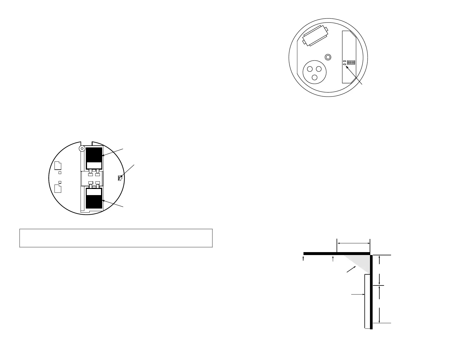
Detectors should be located as close to the center of the ceiling as possible. If
this is not practical, detectors may be located on the ceiling up to 4 inches (10cm)
from the ceiling-wall junction. Do not install near forced air heating or air
conditioning ducts (outlets or returns). For sloped, gabled or high-peaked
ceilings, detectors must be mounted between 4 and 6 inches (10 and 15cm) from
the highest point in the ceiling.
Detectors may also be wall-mounted if permitted by local and state codes. Check
with your local Fire Department about code requirements. Wall-mounted
detectors should be located 4–6 inches (10–15 cm) from the ceiling. In mobile
homes, battery-operated detectors are not generally installed by the
manufacturer. Mount detectors ONLY on an interior wall.
DEAD AIR
SPACE
4 IN.
(10 cm)
CEILING
BEST IN
CORNER
ACCEPTABLE
HERE
ACCEPTABLE
HERE
NOTE:
MEASUREMENTS
SHOWN ARE TO THE
CLOSEST EDGE OF
THE DETECTOR.
SIDE WALL
NEVER
HERE
4 IN.
6 IN.
(10 cm)
(15 cm)
 Loading...