.-.
WWR AND CIRCU~ BOARD—
HOWINGPOSTS[21
WOOKCOVERONTH=E
HEN REPUCINGm
LOCKINORELmEACCE=
W REL=SEUN!T\
FROMWAWPWTE,
INSEmSRWDBIVERBUDE,
P~SSSkUINSTLOCKINGTAB,
ANDSLIDEUNITUp.
CIRCUIT 00ARO HOLDING TAB—
(BEND WCK IF NECEWRY
TO REMOE BOARD)
R
12~ lNP~
AmRMREmVCONTACT[N.c.OPENONAURM,
ED REMOEDISABLEWEN 7WC APPLIEW
r
~OUBLE OUP~ FOR SUPERWSlON.
.USE SHIELDED WIRE FOR UL lNSTALMn~S
4111
(+)(-)AttI-L
123458~!
: . .. ... . . .
MICROWAEDHEmOR
(DRO)
RED LED GREEN LED
(SEE BELOW
(SEE BELOW
b WIRING ENmY HOE
AND WIRING CWNEL
IN BEE
, MICROWAE SENSlnMW
CON~OL.
NRN CLOCWISE M
INCRUSE ENS~lVIN
. PIR D~CTOR
y “LOOK-NW” LENS
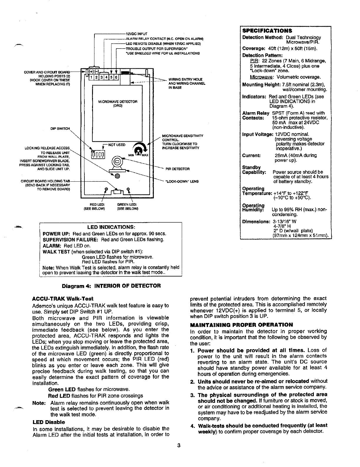
LED INDICATIONS:
POWER UP Red and Green LEDs onforapprox.90 sem.
SUPERVISION FAILURE: Red and Green LEDsflasfdng.
ALARM:
Red LED on.
WALK TEST (when
selectedvia DIP switoh #l ~
Green
LED flashesformicrowave.
Red LED flashesfor PIR.
Notw When Walk Testis selected, alarm relay is constantly held
open to prevent leaving the detec~r in the walk test mode..
c
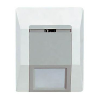
Magram 4 INTERIOR OF DETECTOR
ACCU-TRAK Walk-Test
Ademco’$ unique ACCU-TRAK walk test feature is es6y to
use. Simply set DIP Switch #1 UP.
Both microwave and PIR information is viewable
simultaneously on the two LEDs, providing crisp,
immediate feedback (see below). As you enter the
protected area, ACCU.TRAK responds and lights the
LEDs when you stop moving or leave the protected area,
the LEDs extinguish immediately. In addition, the flash rate
of the microwave LED (green) is directly. pr~otiional to
speed at which movement occurs; the PIR LED (red)
bhnks aa you enter or leave each zone. This will give
precise feedback during walk testing, so that you can
easily determine the exact pattern of coverage for the
installation.
Grasn LED flashes for microwave.
Rsrf LED flashes for PIR zone crossings
Note Alarm relay remains continuously open when walk
,.-
test is selected to prevent leaving the detector in
the walk test mode.
LED ~sable
In some installations, it may be desirable to disable the
Alarm LED after the initial tests at installation, in order to
SPECIFICATIONS
Oe&ction Mathod DualTechnology
Mcrowave/PiR.
COvaraga 40ft(12m)x50ft(15m),
Oetection Pattern:
~ 22 ZOnes (7 Main, 6 Mdrange,
5 Intermediate, 4 Close) plus one
.Look-down. zone.
Mcrowave: VOlumetfic covemge.
Mounting Helghk 7.5ft nominal (2.3m),
walllcomer mounting.
Indicators Red and Green LEUS(see
LED INDICATIONS in
Diagram 4).
Alarm Relay SPST (Fore A) reedwith
COnmo*.
15-ohm
protective resistor,
50 mA max at 24VDC
(non-ind.ctiva).
Input VohagS 12VDC nominal.
(&J::$::::~etector
inoperative.)
Current 25mA (40mA during
power UP).
Standby
CapabiliW Powersourceshouldbe
capableof at least4 hour!
of batte~ stindby.
Operating
Temperature +14°F to +122-F
(-lo~c to +50”C)
Operating
HumidiW Up to 95Y. RH (mW.) non-
condensing.
Dimensions ~-~~~~e:W
.
2“ D (w/wall plat”)
(97mm x 124mm x 51mm)
prevent potential intruders from determining the exact
timits of the Drotected area. Tfds is accomDtished remotelv
whenever 12VDC(+) is appfied to terminal 5, or local&
when DIP switch position 3 is UP.
MAINTAINING PROPER OPERATION
In order tf2 maintain the detector in proper vvorking
condition, it is impoftant that the following be obsewed by
the uaec
1. Power should ba provided at all times. Loss of
power 10 the unit will result in the alarm contacts
reveting to an alarm state. The uni~s DC source
should have standby power available for at least 4
hours oi oDeration duflng emergencies.
2. Units alhould never be r*aim6d or relocaiad without
the advice or &sistance of the alarm sewice company.
3. The physical surroundings of the protected srea
should not ba changed. If furniture or stock ia moved,
or air cclnditioning or additional heating is installed, the
system may have to be readjusted by the alarm aewice
company.
4. Walk-tests should be conducted frquently (at least
wsakly]l to confirm proper coverage by each detector.
3
 Loading...