Industrial Electronic Devices
ADFweb.com S.r.l.
Document code: MN67507_ENG Revision 2.400 Page 28 of 45
Figure 3c: “Set Communication
Operation Mode”
window
Figure 3d: “Set Communication
Modbus Master”
window
O
PERATION
M
ODE
:
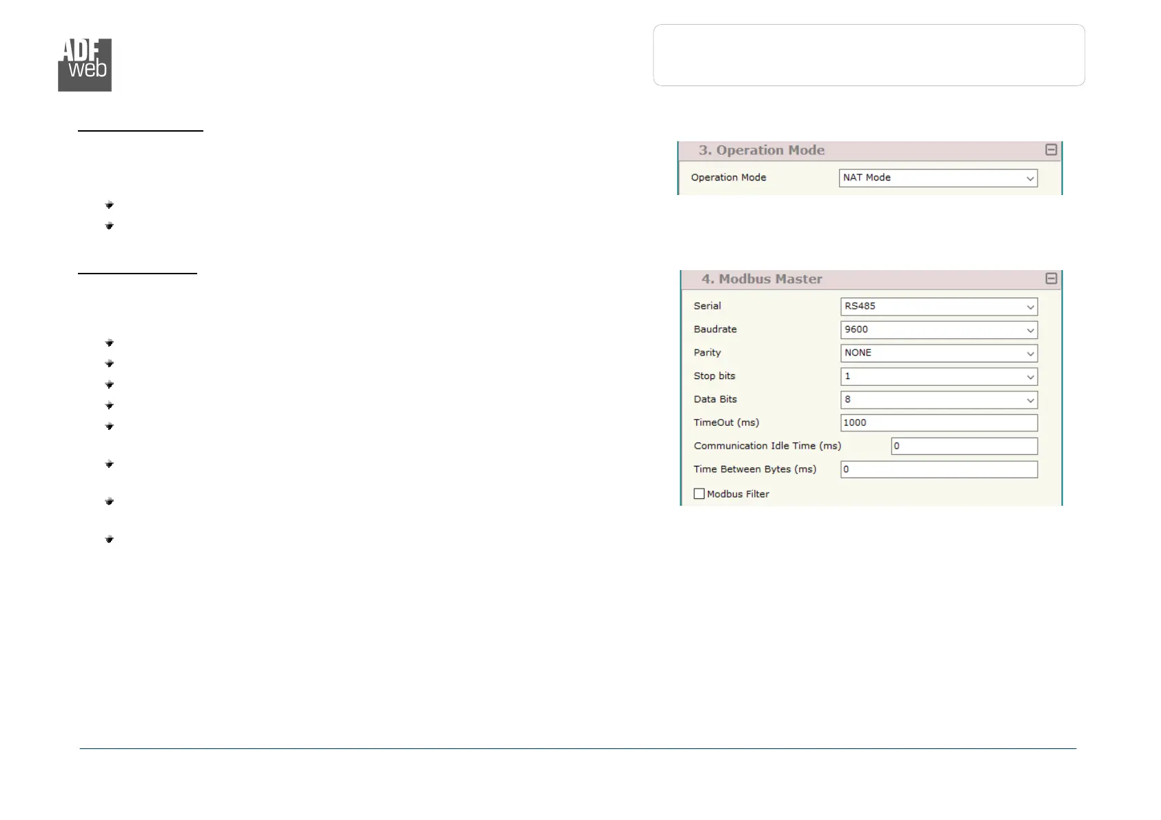
In the section “Operation Mode” it is possible to define the working mode of the
converter (see page 33 for more info):
Routing Mode;
NAT Mode.
M
ODBUS
M
ASTER
:
This section is used to define the main parameters of Modbus line. The means of the
fields are:
In the field “Serial” the serial port to use is defined;
In the field “Baudrate” the baudrate for the serial line is defined;
In the field “Parity” the parity of the serial line is defined;
In the field “Stop Bits” the number of Stop Bits of the serial line is defined;
In the field “TimeOut (ms)” the maximum time that the converter attends
for the answer from the Slave interrogated is defined;
In the field “Communication Idel Time (ms)” the delay (idle time)
between two Modbus requests is defined;
In the field “Time Between Bytes (ms)” a custom delay between the bytes
is defined;
If the field “Modbus Filter” is checked, the filter for the not Modbus frames
is defined;