OPERATING AND USER MANUAL Q-12 CoaXPress series
________________________________________________________________________________________________________________
_________________________________________________________________________________________
Adimec 12
4.2 Electrical interfaces
4.2.1 Power and CoaXPress connectors
The CoaXPress interface supports communication in two directions. Power, control data and trigger signals are
transferred from the frame grabber to the camera and video data is transferred from the camera to the frame
grabber. The function of each connector is listed in Table 4-1. The CXP configurations that are supported by the
camera are listed in Table 4-2.
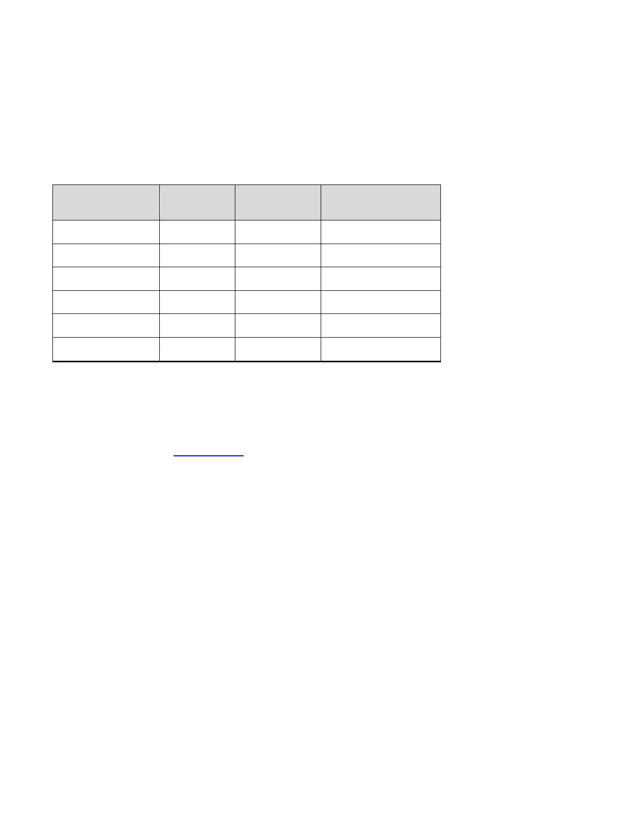
Table 4-2: The supported CXP configurations.
Compliance Labeling
Maximum cable length
(Belden 1694A)
NOTE: Always connect CXP connector 0 as it supplies the camera with power according to the Power over
CoaXPress standard (PoCXP, max 13W).
NOTE: CXP connector 0 is identified by the triangular arrow symbol on the camera housing.
For a complete description of the CoaXPress interface standard please refer to the CoaXPress specification that
can be downloaded from http://jiia.org/en
.
 Loading...