Appendix A — Technical Aspects 19
Note that for either mode the trigger signal must be present for at
least 5 µs to register as an event. When a trigger event occurs, the
trigger indicator light will glow yellow.
When set up through software to use a voltage level, a trigger event is
registered when the voltage exceeds 2.9 volts. The trigger input is
optically isolated when set up for a voltage level. In the external
contact closure mode, the trigger input will respond to a direct short
between the centre pin and outer ring of the BNC. This can be
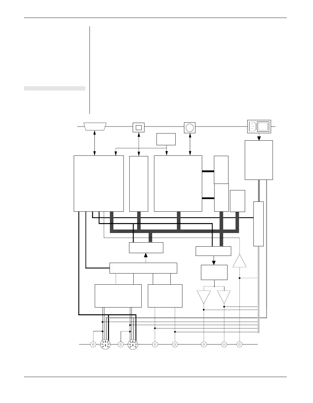
Figure A–2
Block diagram of the
PowerLab 4/20.
PPC403 CPU
16-bit ADC
16-bit DAC
RAN GE
C ON TROL
Switching
Power
Supply
Comparat or
FLASH ROM
1M x 16 DRAM
MULTIPLEXER
System
Glue
Chip
+1 –1
2 Differential Input
Am plif iers
2 Single- ended Input
Am plif ie rs
MultiPort
POD I C
±5 V
USB C ont roller
1M x 16 DRAM
30 MH z
XTAL
2
IEC Mains
Input
USB Port Serial PortI C Port
2
REAR
PANEL
FRONT
PANEL
Analog Inputs Analog Output
External Trigger InputInput 1 Input 2 + –Input 3 Input 4