-)
' \
adler
104VN-2;
-
102;-4102.
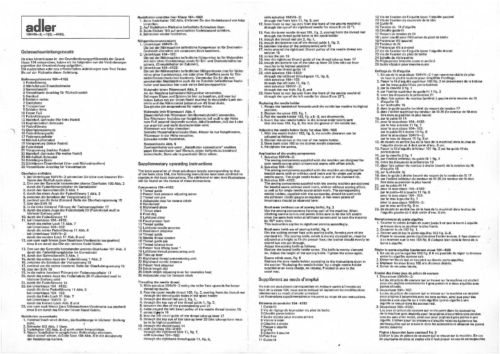
Gebrauchsanleitungszusatz
Da diosc Unterktnsson in
dcr
Grundbcdicnun!] grOBtcntcils
dcr
Grund
-
ktessc
104
cntsprcchcn,
hobcn
wir
im
folgondcn
nu
r
dio
Vor3ndcrun9cn
gegenUbcr
dcr
Grundanlcitung
oufgcfuhrt.
Oio zusiitzlichcn
oder
neu
crfordcrlichcn
Abbildung1m z
um
Text
findon
Sie
ouf
dcr
RUckscite
dicsor
Anlcitung.
Bodionung
sc
lcmcnto
104-4102
1 Fodenfuhrung
2 Niihfulldruck-Einiacllschr.lubc
3 Garnrollenstih
4
Vcrst
o
llbarcr
Anschlag fur RUckwiirtsstlch
5
Handrad
6
Schlobor
rcchts
7
Stichplattc
8
Tronsponour
9 Schieber
links
10 Fester
Fu8
11
FodEmfuhrungcn
12
Nadclbef
.·Schrnubc
(fUr
linkc
Nadel)
13
Kopf
dcckolb
cf
.-Schr.iubc
14
Fndenfuhrung
15
Obcrfodcnsponnung
16
F
adcn
filhrungsstift
17
Fndomrnzugsfodor
18
Nfihfull-Liifterhcbcl
19
Vorspannung
!linker
Faden)
20
F.idenhebel
21
Vorsp:mnuna
lrechtcr
Fcdcnl
22
Nodclbef.
-Schrnube
(fur
rechte
Nadell
23
N5hfullbcf.-Schraubc
24
Stichliin!]Cn·Skolo
25
Stichl5ngen-Ein~cllhcbcl
IVor-
und
RUckw5rtsniitrnnl
26
Vcrstellborer Anschlo!] fiir
Vorwiirt~tich
Oborfoden oinf5doln
1. Bci
Unterktassc
104VN-2
schwenkcm Sic
bittc
zum
bcsscren
Ein-
fodeln
den
RollfuB
noch
obcn.
2.
Oen van
dor
Gornrollc
kommendon
oberon
Oberfodcn
100
Abb.
2
du
r
ch
dle
Fodcnfilhrungslticher
im
Gornstfindor
3.
durch
den
Garnrollcnstih
3
Abb.
1
4.
durch
dils
obcrc
Au!]C
dcr
FDdenfuhruno 1
Abb
. 2
5.
zwischon
dio
Schelbcn
dcr
Vorspannung
21
6. zweimill
um
dio
linko
(hintcrot
Rolle
dcr
Oberfodensponnun!J
15
7.
Uber
den
Stilt
16
8.
In
die
linke
(hintcrc) FUhrung
dcr
Fadcnanzu!]~fcdcr
17
9.
durch
das
obore
Auge
des
Fndenhebels
20
{Fadenhobol
mull
in
hOChster
Stcllung
sein)
10.
durch
die
Fadonfuhruna
14
11.
boi
Unter
kln
sso
104
-4
102:
durch
das
rc
cht
c
Lo
ch
11
Abb.
7
bei
Untcrklasse
104-102:
durch
die
rechte
Fodcnfi.lhrung 11
Abb.
6
bei Untorklns.so
104VN-2:
durch
d.:is
vordero
Loch
11
Abb,
8
und
12
.
van
vorn
mich
hinten
(von
Maschinen-Vorderseito
aus
aosnhon)
otwil
8
cm
durch
das
dhr
dcr
rechten
N
odc
l fodeln.
13.
Oen
van
der
Garnrolle
kommenden
unto
ro n
Obcrfaden
101
Abb.
2
durch
dio FodenfuhrungslOchor
im
Garn
st
ti
nder
14.
durch
den
Garnrollenstift
3
Abb.
1
15.
durch
d~
untere
Augo
der
FDdonfuhrung 1
Abb.
2
16.
zwischcn
dio
Schciben
der
Vorspannung
19
17.
nveimill
um
die
rcc
ht
e (v
ordere)
Rolle
der
Oberfadensponnung
15
18.
Ubnr
dnn
Stift
16
19.
in
die
rechtc
(vordorc) F
i.ih
run!]
dc
r Fodcnunzu!]sfcder
17
20.
durch
dns
untere
Auge de:;
Fode
nhobols
20
(F
adenhebel
mun
in
hOchstt!r
Ste
llung sein)
2
1.
durch
die
Fndenfuhrung
14
22.
bci
Untc
rk
losso
104
4
10
2:
durc
h
die
lin
ke
Fod
enfilhru ng 1 T
Abb.
6
bci
Unt
c
rk
lasse
104·
10
2:
dureh
dos I inko L
oc
h
11
Abb.
7
bcl
Untorklassn 1 D4VN
-2:
du
r
ch
d.is
hintc
ro
Lech
A
bb.
8
und
23.
von
vorn
nach
hint
cn
{von Nfihm.i
schinc
n-Vorder
sc
it
c
aus
gesehen)
etwa
8
cm
durch
dns
bhr
der
Hnken Nadol fiidcln,
Nadolh.altor
.au
s
wochscln
1.
Handrnd
(noch vorn)
drchc
n,
bi!. ND
dolstange
in hOchster
Stc
llung
steht.
2.
Schro
ubo
102
Abb.
1 I Osen.
3.
Nadelholter
103
Abb.
6
-8
nach
unte
n
hcro
uszieho
n.
4. Neuen
Nade
lholter in
umg
ekehr
ter
Roihenfolgc
einsctzo
n,
dobci
dnrouf
Dchten,
doll
die
Nose
104
A
bb
. 8
in
die
Aussporung
dcr
Nadelsumge
kommt,
N.adelhaltor vorstcJlon
tnur
Klasse
104-102)
1. Bcim No
dclholtcr
103
Abb,
6 kOnnon Sic drm
Nadcl.ibstand
wic
folgt
vcrstcllcn:
2.
Auf
N
ode
lhuh cr-Ri.ickseite
befindliche
Schrnuben
IOsen.
3.
Seide
Klobon
105
ouf
gewilnschtcn
Nadelobstand
schicbcn.
4.
SchrmJbcn
wicder
fcstdrchcn.
Niihgiirniturcnonwendung
1.
Unterklasse
104VN
-
2:
Die
be
i
dcr
Ntihmaschlnc befind licho
N5hgarnitur
ist fur Zwcimxfcl-
Grobstlch·Zi
e
rnahte
mit
vorr.otztem
Stich
bcstimmt.
2.
Unt
erklasse
104-102:
Die
bei
dor Niihmaschine
befindliche
N5hgornitur
ist
fur
Wulstniihto
mit
odor
ohne
Kordelcinlage
sowie
fur Ein- und Dreinadotnfihte be-
stimmt.
tE
in
nndelhattcr
Im
ZubchOrl.
3.
Untcrklossc
104-4102:
Die boi dor
N5hmaschino
befindllchon
NUhaarnituron sind fur Wul!it·
1
n5htc
ohnc
Kordclei
nlugo,
mit
oder
ohnc
Ritzcffe
k t sowie
fi.ir
Ein-
r1adel-Grobsticharbeiton
bostimmt.
Vct"Nenden Sie fur
dio
cnt·
spre
chondcn NadelstDrken
auch
die
im
Zub
ohOr
beflndllc
hon Nadel-
hnltor
und
beochtcn
hier
noch
cinigo
Bcdicnungspunkte;
Wulstnaht
lohnc
Ritzmouur)
Abb.
3
An
dcr Maschino
befindlichc
N.5hgornitur
vorwcndon.
Boi
cngon BOgcn
und
Spltzcn
1st
hlcr
zu
boachton,
dall
man
boi
linken
Ecken
mit
dor
linkcn
Nodal zweimal in
das
gleichc
Loch
ein-
sticht
und
da
s Niihmotorial jcdesmol
um
45
Grad
dr
eh
t.
O
as
gleicho
gilt
entsprochend
fur
rochte
Eck
en.
Wul5tn.aht
(mit
Ritzmesser)
Abb.
4
Bicsonniihfull
mit
Ritzmes
s
er
(Im NormalzubehOr)
vcrwenden.
Oas
Ritzmesser
(welchcs
nur
feSlgcklemmt
1st}
muB in
der
HChe
zum
Fu8
passcnd
eingcstcllt
wcrdcn,
dobci
beochton,
dall
dils
Loder
nur
ongcritzt
und
nicht
durchschnitten
wird,
Rltzmessor
wie
folgt
clnstellen:
Soitlicho Mcsserholterschrilubo
IOSon.
Me:.ser
ist
nur
fcstgeklcmmt.
Ritzmesscr
in
dcr
Hfiho vcrstcllcn.
Schraube
wiodcr
fcstdrehon.
Grobstichnaht
Abb.
5
Zwoinndelha
lter
wio
unter
,.Nadelhalter
ouswechsoln"
on.viihnt
gogcn
Einnodelholter
{auf Wunsch,
9eg1m
Aufprois
zu
boziehcnl
ouswechs
e1
n. Dann
wio
in
gewohntcr
W
eise
n5hcn.
Supplementary
operating instructions
The
bas
ic
operntion
of
these
sub-classes
largely
corresponding
to
that
of
the
basic
cla~
104,
the
follow
ing ins
tructions
have
been
confined
to
chong8s in
the
basic
instru
ction
s.
The
additio
n
al
or
new
toxt
illustrotions
will
bo
found
on
tho
ro-11cno
of
theso
instructions.
Components
104
-4
102
1
Throad
guide
2
Prosser
foot
pressure
adjusting screw
3
Thread
rcol
pin
4
Adjust
nblo
stop
for
reverse
stitch
5 Hondwheol
6
Righthand
slider
7
Throot
plote
B
Feed
dog
9
Lofthnnd
slider
10
Fix
ed
presser fo
ot
11 T hrcud gu id
!!S
12
Lof
thond
needle
setscrew
13
Head
cover
tOtscrcw
14
Thread
guide
15
Necdlo
thread
ten
sion
16
Thread
gu ido pin
17
Throod
take-u
p lov
er
18
Presser
foot
lifting
l
ever
"'
19
L
efthand
thread
prete
nsioning
unit
20
T ilko-up lev
er
21
Aighthand
thread
prctcnsionin!]
unit
22
Righthand
needle
setscrew
23
Presser
foot
setscr
ew
24
Stitch
length
dial
25
S
titch
len
gth
adjust
ing lever
for
reversible feed
26
Adjustable
stop
for
forward
stitch
Threading
the
needle
thro
-,d
1. With sub-class
104VN-2
swing
th
e roller
foot
upw
ar
ds
for
b
etter
thread
ing
re
i:
ults
.
2.
Pnss
the
uppor
needle
th
read
100,
fig,
2,
com
in!]
from
th
e t
hre
ad
ree
l
through
the
thread
guide
hales
in
the
s
pool
holder
3.
through
Jhe
thr
eild reel
pin
3,
fig. 1,
4.
through
th
e
top
eye
of
t
he
thre
ad
guide
1,
fig.
2,
5.
between
tho
di
sc
of
the
pr
et
ensioning
unit
21
6.
t
wice
around
the
lort
troar)
pu
lley
of
t
he
neodlo
thr
e.id
tension
15
7.
across
tha,Jin
16
8.
into
the
10ft
(read
guido
of
the
threa
d
tuke
-
up
lever
17
9.
thro
ug
h
the
top
eye
of
the
take-up
lover
20
(the
take-up
lover
must
be
in its hi
ghest
po
sit
ion)
10. t
hrough
the
thrcnd
guide
14
11. w ith sub-class
104-4102:
t
hro
ugh
tho
rfahtho
nd
hole
11,
fig.
7.
with
sub-clDss
104
-
102
:
through
the
righthilnd
th
rcod
guido
11,
fig.
6,
with
sub-closs
104VN-2:
through
the
front
hole
11,
fig .
8,
ond
12.
from
front
to
rear
(as seen
from
tho
front
of
tho
sewing
muchinel
throu!]h
tho
eye
of
the
righthond
needle
for
about
8
cm
13
"I.
13. Pass
the
lower
needle
thr
eod
101,
fig. 2,
coming
from
the
thread
reel
through
the
thread
guide
halo~ in
the
spool
holder
14.
trough
the
thrc
od reel
pin
3,
fig.
1,
15.
trouoh
the
bottom
eye
of
the
th
rm:i
d
guide
1,
fig. 2,
16,
between
the
di~
of
the
pretens
io
ning
unit
19
17,
twice
around
the
righthond {front) pulley
of
the
necdlo
thread
ton
tension
15
18.
Deross
the
pin
16
19.
into
the
righthand
(from}
guide
of
the
thread
tnke-up
lever
17
20.
trough
the
bottom
eye
of
tho
toke-up
lever
20
(the
tDke-up lever
must
be
in i
ts
highost
position)
21.
through
the
thread
guide
14
22
.
with
sub-class
104
-
4102:
through
the
lcfthond
thread
guido
11,
fig,
6,
with
sub-clau
104-102;
through
the
left
hole
11,
fig.
7,
with
sub-class
104NV-2
:
through
the
rear
ho
to, fig.
8,
and
23.
from
front
to
roar
(o!i
seen
from
the
front
of
th
e
sewing
muchine)
through
the
eye
of
tho
l
eft
needle
for
ubout
8
cm
{3")
.
Ropl.aclng
tho
neodlo
holdor
1.
Rotate
the
handwhecl
for\.'11ards
until
tho
needle
bar
reaches
its
highest
position.
2.
Slacken
t
he
screw
102,
fig.
1.
·
3.
Pull
the
needle
holder
103,
fig. s
6-8,
out
downwards.
4.
Insert
the
new
needle
holder
in
tho
invcr,e
order
toking
core
thot
the
nose
104,
fig.
a,
fits
into
the
groove
of
the
needle
bar.
Adjusting
tho
neodlo
holdor
lcnly
for
class
104-1021
1.
With
tho
needle
ho
l
dor
103,
fio.
6,
tho
needle
clcanmce
can
bo
adjustod
os
follows:
2.
Slacken
the
screws
ot
the
rear
of
the
need
le
holder
.
3.
Move
bath
vices
105
to
the
desired
needle
clearonce.
4.
Ac-
tighten
tho
sc
rews.
Application
of
the
sowing
compcmmts
1.
Sub-class
104VN-2:
Thu
.sow
ing
components
suppliod
with
tho
machine
arc
designed
for
twin
needle
coorse
stitch
ornamental
sccJms
with
offset
stitch.
2. Sub-class
104-102:
Tho
sewing
ccmpononts
suppliod
with
tho
machine
ore
dcsignod
for
beaded
!.cams
with
or
without
cord
inse
rt
and
for
singlo
and
trlplo
needle
scams.
The
single
needle
holder
is
part
of
tho
standard
kit.
3. Sub-class
104-4102
:
The
scwin!]
components
supp
lied
with
the
sewing
machine
ore
designed
for
beaded
s0.am5
without
cord
ins
ort,
with
or
without
scoring
effect,
as well as for single
needle
coar:;c
stitch
worl:.
The
corresponding
noodle
ho
lders,
suppliod
with
tho
ocecssaries,
sho
uld
be
used
with
tho
difforont needlo gouges os
required,
A fow
more
points
of
importance
should
be
obse
rved
hero:
Bond scam
twithout
use
of
scoririg knife}, fig. 3
Uso
the
sewing
components
farming
pan
of
the
machine.
When
stitching
narrow
curves
and
points
mokt!
sure
to
let
the
feft
need
le
enter
the
some
hole
twice
at
lef
thond
corners
and
to
turn
tho
materiol
by
450
every
time.
T his
instruction
opp
lies
to
ri
gh
th
a
nd
corners
accor
dingly.
Bead
scam
Cwith
usc
of
scoring knlfo), fig. 4
Use
the
welting
pro~er
foot
wi
th
scaring
knife, forming
part
of
tho
.st
an
da
rd
kit.
The
scoring
knife,
which
is
merely
clamped
on,
must
bo
adjusted
at a
he
ig
ht
to fit
tho
presst!r f
oot;
the
leat
he
r
should
merely
be
scored
but
not
cut
th
roug
h.
Adjust
the
scoring
knife
os follows:
Slockcn
the
lateral
knife
holder
screw.
Tho
knifo
is
merely
cl.ampod
on,
Adjust
the
height
of
the
sco
ring
knife.
Tighten
the
screw
ogoln.
Coorso s
titc
h scam, fig. 5
Replace
the
twin
need
le ho
lder
according
to
th
o
instructions
given In
th
o
section
' Aeplucino
the
n
eed
le
holder'
by
a single
needle
holder
suppl
i
ed
.it
.in
extra
chargi!,
on
request.
Proceed
ta
sew
in
the
usual
way,
Supplement
au
mode
d'
emploi
Vu
quo
c
es
!.Ou
s-
classes
corre
s
pon
de
nt
en
ma)eure
panic
a
rcmpl
oi
de
ba
se
do
lo
clossc
104,
nou
s ovons indiquC ici seul
emen
t
lc
s
mod
ific
atio
ns
relative
me
nt
au
mode
d'emp
l
ol
principa
l.
Les illustrations
supp
t
emento
ir
es
sc
trouvent
ilU
verso
de
cos in
struc
t
ions
.
E)6monts
do
conduitc
10
4
-4102
t
Guide
-rn
2 Vis d e rCglage de lo
pre~
ion du
pied
de
bich
e
3
Cht!villc
port
e-b
obinc
4 ButCo r~glabo
pour
marchc-arri!!?rc
5
Volant
ii
mo
in
6 GlissiCre
iJ
droitc
7
Plnque
n oiguillc
BGriffe
9
Gl
is
si~
re O gouche
10
Pied
fixe
11
Guidc
,fil
12
Vis
de
fixation
de
l'niguitlc
(pour
l"aiguillc gouc
hel
13
Vis
de
fix.ation
du
couve
rclo
do
la
tl)tc
14 Guide-Iii
15
Te
nsion
du
fil
d'o
iguille
16
Cheville guide·fil
17
Rcssort
de
tension
de
fi l
18
Levier
coud6
pour
1'8
fCv
iltion
du
pied
de
bicho
19
PrCtcnsion lfil gaucJ1cl
20
Tendeur
de
fil
21 PrCtcnsion lfil
iJ
droitel
22
Vis
do
fl
xot
ion
do
l'ai9uille !
po
ur
l'a
iguille
droitc)
23
Vis
de
fixntion
du
piod
de
biche
24
Echellc
du
rCglc-points
25
RCg
l
e-points
(murchc
avant ot arriCre)
26
But
Cc rCglablc
pour
morche-av,:mt
EnfiliJgo
du
fil d'iJigu illo
1.
En
ens
de
la sous·cliJsse
104VN-2
ii
est
recommilndoblc
de
plier
en
hout
le
pied
iJ
roulette
pour
Simplifier l'onfilnoa.
2,
Passer
le
fil d'ai!]uille supC
rie
ur
100
fig, 2
en
provenance
de
la
boblne
par
lcs
uous
guide-fil
du
portc-Ucbincs
3.
par
la chuville 3 fig. 1
4.
par
l'oeillct
supt'.:rieur
du
guitle-fil 1 fig, 2
5.
ontrc
les
disques
do
lo prCrnnsion
21
6.
deux
fois
outour
du
roul
e.iu lorriCrel a gauchD
de
la
tension
du
fil
d'oiguille
15
7.
su
r
lil
chcville
16
8.
da
ns
le guido
gauche
lorrillrel
du
ressort
de
tension
17
9.
dens
l
'ooillot
supCrieur
du
tondeur
de
fil
20
(lo Ulndeur
de
fil
doit
t!tre diJm;
SiJ
posit
ion
la
plus
hautc)
10.
par
le g
uidc
.fil
14
11.
pour
lo
~us-classe
104-4102
:
par
I!!
trou
a
droitc
11 fig. 7
pour
la
sous-cla!so
104-102:
p.ir le guide-fil O
droitc
11 fig. 6
pour
lo
sous-cJasse
104VN-2:
par
le
trou
de
deva
nt
11
fig. B
et
12.
de
deviJnt
en
arriere
(vu
de
la foce
de
lo
mach
ine)
duns
le
chos
do
l'aiouille
droite
olJ
ii
doit
sortir
d'env.
8
cm.
13. Passer lo fil
d'aiguille
infCrieur
101
fig. 2
par
les guide-fil
du
porte-bobine
14.
par
la cheville 3 Hg. 1
15.
par
l'oeillot
lnfCrieur
du
guidc-fil 1 fig, 2
16.
cntre
les
d i;.ques
de
lo
prCtension
19
17,
deux
fois
autour
du
rouleau
D
dro
ite
(nvontl
de
lo
tension
du
fil
d'aiguillo
ts
18.
s
ur
lo
ch!!Villc
16
19.
dons lo guido it
draito
h:iv
nntl
du
ressort
de
lo
tomion
do
fil 17
20.
por
l'ocillet
infi:rieur
du
tend
o
ur
de
fil
20
(le
tcnde
ur
de
HI
doit
Otre
dan
s
!D
position
la
plus
hautel
21.
p.ir le guide-Iii
14
22.
pour
la
sous-classo
104-4102:
par
le
guidc-fil
ll
g
il
uc
he
11
fig, 6
pour
la
sou::.-classe
104
-
102:
pur le
trou
ii
gauche
fi!],
7
pour
la
sous-classc
104VN-2:
p.1r
le
trou
arr
i0ro fig. 8
et
23.
de
devont
en
nr
riCre (vu
do
la face
de
la
mochine)
dans
le
chas
de
l'aiguille ga
uc
he
oU
ii
doit
sortir
d'env.
B
cm.
Rcmplacoment
du
parte-aloullles
1.
T
ourner
le
volant
a
main
en
il"lant jusqu'l.l
co
quo
la
barre
a .iiouillc
so
t
ro
uvc
dans
sa
position
lo
plus
hau
te,
2.
Dess
errcr
lo
vis
10
2 Hg. 1.
3.
Retiror
vers
le
bas
le porte-aiguil!cs
103
fig.
6-8.
4. Pl
acer
le
nouveau
par
te-ulguilles
dan
s
l'ordro
inverse,
ii
fo
ut
ob!;Crver
a
co
moment
que
le ncz
104
fig. 8
s'adapte
bien
dans
lil
fen
to
de
1
11
bnrre
il aiguilla.
RCglcr
lo
porto-
aiguillcs
(sculomont
clnsse
104-4021
1.
En
cos du port1H1iguillos 1
03
fig. 6
ii
est
possible
de
rt!gler la
distance
entro
les
niguillcs
comme
suit
:
2. Ocsserr
er
lcs vis
qui
so
trouvcnt
au
d os
du
po
r
te
-oiguill
cs
.
3.
DC
placer
lc
s
dcux
blocs
105
i:I
In
distance
d0
slr6e.
4.
Se
rr
er
de
nouv
eau
l
es
vis.
E
mploi
des:
divers jeux
do
piOcos
do
couturo
1.
Sous
-d.a~ o
t04VN
- 2: ·
Le
je
u
de
piCccs de
cou
ture
qui
~e
tro
uv
e
sur
la
machine
est
cfostin
f!
pour
de
s piqUres
ornemontale
s
il
gros
po
int
s
et
i:I
dcux
oiguilles
ilVCC
poin
ts
dCcalCs.
2.
Sou
s-
classc
104-102:
Le
jcu
de
pi
Ccos
de
couturn
qu
i so
trouve
sur
la
machine
est
destint~
po
ur
piqOres ii
bourre
lets
ovoc
ou
s
ans
cordon
, ainsi
que
pou
r
des
piQOrcs
ii
une
alguillo
ou
O
trois
oi!]uillas
lport
c
-a
iguiUe a
unc
oigu illc
sc
trcuve
dilns los accossoircs}.
3.
Sous-c
lassc
104
-
4102:
Los
je
ux
de
piCces
de
couture
qui
so t
rcuvent
dons
le
s occcsso
ir
es
de
la
machine
sont
destin~s
pour
!es piqOres
ii
bourrolcts
sans
cordon
Jvoc
au
s
ans
11ffet
incise. ainsi q
ue
pour
piqUrcs a
gros
point
s O
uno
aiguillo, Utiliser
po
ur
l
es
gras~ours d'aiguillo relotivos ~
go
lnm
cnt
le
s
pcrte-aigu
illes qui se
trouvent
da
ns fes Dccessoi
res
et
observe
r les
po
in
ts
point
s suivants:
PiqUro
il
bourrolet
ISi!n
s
coutn:iut
fig. 3
l,.hiliser
le
jeu
de
pi~ces
de
couture
q ui
so
tr
o uve
sur
la
machine.
En
ens
de
cou
rbur
es
~troites
ct
angles
vHs
ii
fout
piquer
en
cas
de
coins
giluchcs
From the Library of Superior Sewing Machine & Supply LLC
 Loading...