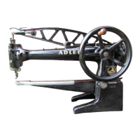
NllhfuBdruck
einstellen
Einstel lschroube 2
Abb.
l
drehen
:
Rechtsherum
= NahfuBdruck stllrker
Linksherum = NahfuBdruck schwllcher
Zum
Nohen
vorbereiten
und nl:lhen
1.
Sponnung (
Vo
lt ) ouf dem Stromzllhler
muB
mi
t
den
Angoben
ouf
dem
Motorschild Ubereinstimmen.
2.
ZufUhrungsstecker mit dem
Netz
verbinden
.
3.
Motor
durch
Schal
ler
46
Abb.
2
einschalten
.
4.
Unterfaden
heraufhalen
(
Oberfaden
festholten
und Handrod einmol
noch
vorn
drehen
)
5.
NllhfuB
durch
LUft
erhebe
l
17
oder
rechtem
FuBtritt Abb. l
luften.
6.
Beide Fllden noch
hinten
u
nt
er
den
NllhfuB
legen.
7.
Nahmoterial
unter
den
NahfuB legen und NllhfuB
senken.
8.
Lin
ken FuBtritt niederdrUcken.
Moschine
nllht.
Je
weiter
der
FuB
tri
tt
durchged
rUckt
wird,
desto
schneller
naht
di
e
Moschine.
Drehrichtung
der
Moschine prUfen. Hondrad
muB
sich
auf
den
Nllhen-
de
n
zu
drehen.
9.
Moschine
ohne
Nllhmoteriol nur
dann
laufen lessen, wenn NahfuB
angehoben
isl.
l 0
.N
ach
dem Nllhen Motor obsc
holten.
Fodensponnung
l:i
ndern
1 •
Noht
nach
einer
kurzen
Strecke
prUfen.
2.
Abb.
9:
oben
= Verschlingung der Fllden ist
richtig.
mitte
=
Oberfadenspon
nung
zu
schwoch
oder
Unterfadenspannung
zu
stark
unten
= Oberfadensponnung
zu
stark
oder
Unterfadensponnung
zu
schwoch
3.
Oberfadensp
onnung mit Spannungsmut
ter
13
bzw.
19
Abb.
l
einstellen:
schwllchere Spannung = Muttern
noch
rechts
drehe
n
st!l
rkere
Spannung = Muttern
noch
links drehen
4.
Unterfadensponnung ml:iglichst
nicht
verl:indern
Fo
I
ls
doch
erforderl
ich,
Schroube
47
Abb,
6 lllsen,
Schraube
48
dr
ehe
n:
stllrkere Spannung = Schroube
48
noch
rechts
drehen
.
sc
hwacher
e Sponnung = Schroube
48
noch
I inks
drehen.
5.
Schi-oube
47
festdrehen.
Reinigen und !lien
1.
Noch
11:lngerer
Betriebsd
auer
oder
Stillstand,
Nahmaschine
re
inigen.
2.
Motor
abscholten,
Netzstecker
entfernen
.
3.
Kopfd
ec
ke
l,
Sti_
chplotte
und
Schieber
entfernen.
4.
Alie .
sichtbaren
Tei le v
an
N!lhrUckstttnden
reinigen.
5.
Bel
lllngerem Stillstond
der
Moschine etwos Petroleum
on
olle
beweg-
lichen
Teile
geben.
•
6.
Maschine
m
it
ongehobenem N!ihfuB
kurze
Zeit
loufen lessen.
7. Schmutz
obputzen.
8.
Nl:lhmoschine Bien. Die
Pfeile
der Abb. 3 und 4
geben
die
erforde
r-
1 ichen
Olstel
l
en
on
.
Nur
unser horz
-u
nd stlu
re
freies Nllhmaschinen
l:ll
MR
3 verwenden.
9 .
Beim
Reinigen und
!:lien
der
Schiffchenbohn
gehen
Sie
wie
folgt
vor:
Hebel
50
Abb. 8 herunterdrUcken (
Deckelfeder
51
kloppt
noch
hinten
).
Schiffchenbohn
deckel
52 von FUhrungsst
iften
53
obheben
und
Barrel-
schiffchen
54
ous
der
Bahn
nehmen,
Die
jetzt
sichtbore
Schiffchenbahn
mit einem
l:l
lgetrl:lnkten
sauberen
Putztuch
ein
l:i
len,
· ·
Borrelschiffchen,
Schiffchenbahndecke
l
einsetzen.
Deckelfeder
zukloppen,
dobei
dorouf
ochten,
doB
Na
se
55
in
Bohrung
56
zu
Ii
egen
kommt. ·
Sollten
noch
irgendwelche
Unklorheiten
bestehen,
bitte
Vertr
eter
oder
Fochberoter
anfardern.
. Bei RUckfrogen
im
Werk
bitte
ongeben
:
1.
Lieferdotum
2,
Klossenbezeichnung
3.
Oberteilnummer
Operating
instructions
Even if
you
are o sewing
machine
expert
you
should
study these
operoting
instructions
careful
ly
ond
fallow
thi, recommendatins gi
ven
.
On
ly th
en
con
sati
sfactory
operation
be
guoranteed.
The following t
ext
applies
only
to
the
bosic
operation
of
the
Adler
104 - l
05
, Wh
ere
the
op
er
ation
of
the
sub - classes differs
from
that
of
the
basic
design,
please
consult
the
supp-
lementary
operating
instr
uct
in
s.
For
better
surrey
please
unfold
the
illus
tr
at
ions
s
hown
on
the
l
ast
page
of
thi
s
guide.
P
lease
note
!
In
order to extend the life
of
the
machine
t
he
sewing speed should
be
r
e-
duced
in
the following cases :
1.
during
the
runnin
g-in
period,
2.
when
processing thi
ck
mate
r
ia
l,
3.
during
conti
nuous operation
over
pr
ot
r
ac
t
ed
periods,
4.
when
using Ion
stitches,
5,
when
complicated
work is i
nvo
l
ved.
Componen
ts
l 04 - 2
l Thread guide
2 Presser foot pressure adjust
ing
scr
ew
3 Threod
reel
pin
4 Adj
ustable
slap for
reverse
stitch
5 Hondwheel
6 Righthond sl
ider
7 Throat
plate
8
Feed
dog
9 Lefthand sli
de
r
1 0 Fixed presser foot
11
Thread
guide
hole
12 Thread
guide
13
Needle
thre
ad
tension
14
Thread
guide
pin
15 Thread tok
e-up
l
eve
r
Unpacking
16
Toke-up
lever
17
Presser foot li
ft
ing
l
ever
18 Head
cover
setscrew
19
pr
etensioning
unit
20
Needle
se
tscrew
21
Presser foot setscrew
22 Stich
indicator
23 S
ti
ch
l
ength
adjusting
le
ver
for
re
ver
si
b
le
fee
d
24 Ad justable stop for forward
stitch
Check
the
packaging
for
damage
in
the
presence
of
the
carrier,
Check
se
wing mach
ine,
stand
and
accessories
for
any
pois
ible
transport
damage.
Immediately notify ony domoge in
the
pres
ence
of
the
ca
r
rier
.
Assembly
1 •
In
the
cose
of
class l
04
:
fit the sewing
machine
info
t
he
round
hinges
30
, fig
.2,
screwed
to
the
stand.
2.
In
the
case
of
class 105 :
screw
the
sewing
machine
to
the
stand
by means
of
the
screws supplied
with
the
st
andard
accessories.
3,
Fit
the
fop
section
support
31
into
the
table
top
hole
.
4.
Screw
on t
he
spdol
ho
l
der
32
en
d
the
power
bobb
in
winder
33.
5,
Piece
the Vee
-b
el
t onta the h
andwhe
el
and
motor
pull
eys. Tension
the
Vee-belt
by swinging
the
motor outwards so thot the
belt
con
stil
l
be
compressed
ot
th
e
cent
re by o
ppr.
15
mm
,
Cleaning
and
oiling
1.
Slacken
the
he
ed
cover
screws
17,
fig.
l.
2.
Remove
the
head
cover.
3,
S
lacke
n the t
hroat
plote
screws ond
re
m
ove
t
hroat
pl
ate
7 as
well
as
sl
ide
r
9.
4.
Screw
on
spool hold
er
32
en
d power bobbin
winder
33.
5.
Lubricate al I points ind
ica
ted
by a rro
ws
in
the
fiA
, s 3 and
4.
6.
Use our oil with following
data
:
Viscosity at
20°
C, cSt:
193
,0
Viscosity at
50°.
C,
cSt
:
41
,0
flash point
°C
:
224,0
Component number 990470128
fo
r 1
·11t
re container.
Component number
990
47
012
9 lor
5-l
it
re
con
ta
ine
r.
Thr
eadi
ng the
need
I e
thread
1,
Poss
the
needle
thread coming from
the
thread
reel
through the
guide
hol
es
in the spool
holder,
2.
Th
rough
the
th
rea
d
reel
pin
3,
fig.
1,
3,
thr
ough
the thr
ead
guides
34
-
36,
f
ig.
_
5,
with the
oil
t
onk
open,
( now
close
oil
ta
nk, The
oil
tank
is
supplied
on
req
ue
st
only
)
4,
through
the
th
rea
d gui
de
l,
5.
between
the tensioning discs
18,
6.
twice
oro
und
the
tensioning
pulley
of
needle
thread
tension 13,
7. across
the
pin 1
4,
8.
in
to
the
th
r
ead
take
-u
p l
ever
15,
9.
through
the
toke
-µp
le
v
er
eye
16
(
the
t
ake-up
leve
r must
be
in its
highest
position )
l
O.
through the thr
ead
guide
1
2,
11
.through the thread
guide
hole
11
ond
12,from
left
to
right
( os
seen
from
the
front of
the
machine
) through
the ne
edle
eye
for
cpp
r. -8 cm (
3"
).
Needl
e
end
thread
1. O
nl
y use n
eedle
system
328.
From the Library of Superior Sewing Machine & Supply LLC
 Loading...