adler
·
105RM-25/~P75
Gebrauchsanleitungszusatz
Oa
diesc
Untcrklos.sc In
der
Grundbedicnung
grOlltentoils
dcr
Grund-
klosse
105
cntspricht,
h.:ibon
wir
im fol!]enden
nur
die
Vcr3ndcrungon
gegcnUber
der
Grund:m
lcitu ng
aufgefuhrt.
Die
zusl:itzllchen
oder
neu
crforderlichen
Abbildungcn
zum
Text
finden Sic our
der
RUckscirn
diescr
Anleit
ung.
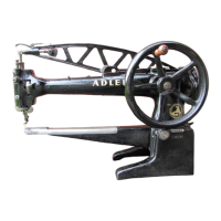
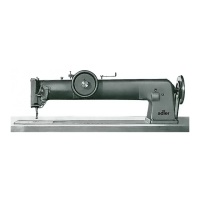
Bcachten
Sie
wcitcrhin,
dall
das
Niihcn diesnr ,.Originnl-Mokassin"
im
1.
Arbciugang
mit
dor
Klano
105RM-25/SP75
und
im
2.
Arbeitsgang
mh
dcr Klome
105
-25MO
hergestcllt
wird.
Bcdienungsclamente
1 OSRM ·
25/SP75
1
Fadenfuhrung
13
Kopfdeckelbcf.-Schr.iubc
2
Niihfufldruck-Einstcllschroubc
14
Fadonfuhrung
3
Garnrollenstift
15
Oborfadcnspannung
4
Handrad
16
Fadcnfi.ihrungsstift
5
Verstellbarcr
Anschlag
17
Faden;,nzugsfcder
fur
Vorw5rtutich
18
Einstellsclm:iube
fUr
NiihfuB.hub
6 Stichliingen-Einstellhcbcl
19
N5hfull·Uif1erhebel
(nur
Vorw5rtsnfihcn)
20
Fodcnhcbcl
7
Raffcinrichtung
SP75
21
Kopfdeckclbef
,
·Schrnube
8
Stichplatte
22
Vo
rsponnung
9
Tr;msporteur
23
Fcststcllmuttcr
fur NOhfuBhub
10
Obcrtra
nsportfuB
24
Nadclbcf.-Schrnubc
11 NiihfuObcf
.-Schraube
25
Stichli:ingen-Skala
12
FadcnfUhr
ung
sloch
N.:ihfuBhub cinstollcn
Der
N5hfu0hub
ist
vom
Werk
aus
cntsprechcnd
dem
Vcrwcndungsiweck
di
eser
Unterkl,me
eingestellt. Werdcn
cxtrcm
diinne
oder
dicke
Materialien
vernliht,
dann
stell!m
Sic
den
NOhfullhub wie folgt ci
n:
1.
Hub
nach
der
St5rkc
des
N5hmaterials
cin~tellcn .
NiihfuB
darf
sich nur
sowcit
Uber
das
Niihmoteriol
onheben,
daB
sich
das
Moteriol frei
bcwcgen
konn.
2,
fcsutollmutter
23
Abb.
1 lin
ksdrchcnd
ICl~cn
.
3. Einstelf~
hr
au
bc
18
drehen
:
Rcchtsherum
c
gr6Bercn
N5hfullhub
Linksherum
a
kleineren
N5hfuRhub
4.
Mutter
23
fcstdrchcn.
Stichli:inge cinstollcn
Nur
Vorwiirt.sstich:
Heb
el
6
Abb,
1
im
Schlitz
verstellen.
Nach
obcn
=
klcincre
Stichlii
nge
N.ich
unten
= gr5Bcre Stichl5nge
Nadal
und
Garn
t.
FUr
den
1.
Arbciugong
verwcndcn
Sic
das
N.idelsystcm
3285
Nr,
140
und
als
Oberfaden
cin
Gorn
124
/3
oder
40/3
foch) in
dcr
Obcrledcr-
farbe.
FUr
den
2.
Arbcit!igang
(ouf
Kl
as
se
10S
-25MO
)
verwcndcn
Sic
das
Nodels
ystcm
328S
Nr.
230
und
als
Oberfadcn
ein
starkes
synthc•
tisches Gilrn (cvtl. Ritzil 1 mml.
2.
FUr
den
1. Arbuits9an9
vurwcndcn
Sic
fu
r
den
Unterraden
dils
in
dcr
Klas!:e
10
5RM-25/SP75
bcfindlichc
Barrelschiffchcn
fur d
Un
ne
s
Gorn
(
24/3
oder
40/3
fach).
FUr
den
2. Arbcitsgang
vcrwenden
Sie
fUr
den
Untcrfaden
das in
de
r
Klilssc
105-25MO
befindliche
zwe
itc Barrel
sch
iffchen
fu
r d
ic
kes
Garn
(1
mm
RitziJ
oder
iihnliches
synthct
lsc
he~
G.ir
n);
Ba
rrobchiffchcn
wcch1oln
Mit
der
Kla
si.
c
105RM-25/SP75
erhalten
Sic
zwei Bar
rclschiffchen.
Eins in
dcr
Mas.chine
zum
Vcrnahen
van
dUnncm G
arn
und
eins
im
Norma
lzube
hClr
zum
Vern5hcn
vcn
dickem
Garn.
1.
Schraubcn
111
Abb
. 5
hcrausdrehen.
2.
Ncues
Ba
rrelsc
hiff
chen
einsct:cn
und
mit
don
Schraubcn
111
~-.iiede
r
fcstdrchcn.
Zum
Niihen
vorbcr
citcn
und
niihen
Wic
schon
am
Anfang
erwoh
nt,
wi
rtJ dies~r Or
igi
nal·MOkiJssin a
uf
2 ver-
schiedenen
Nc1hmnschinen
gesteppt.
Als
1.
Arbe
it
sg:mg
wird
das
Bodenteil
nn
das
Herzeinsatzstilck auf
Kl.is~e
105AM
-
25/SP75
angcrafh
.
Gehen
Sic
deshalb
wic
folgt
vor;
1.
Spannung
(
Volt)
nuf
dem
Stromz4hl(!r
muR
m
it
den
Angobcn
ilUf
dem
Motorschild
Ubereim
t
imme
n.
2.
Zu
fi.i
hrungsstocke
r
mlt
dcm
Netz
vcrbinden.
3.
Motor
durch
Sch:iltcr
(rcchts
vorn
om
Gcste/1)
einsc
h
alten.
4. Untl!rfoden
heraufhalen
(Oborfa
d
on
rcst
ha
lt
en
u
nd
Hilndrad cin-
mal
nac
h
vorn
dr
c
hcn.
5.
Ni:ihfuB
du
rch Liifte
rhc
bel
19
Abb.
1
luften.
Ci.
Beide
Fiidcn
m1ch
hinten
unt
er
den
N
ti
hfu8.
lc
gen.
7.
Bodente
il
un
d Herzeinsatzstiick an
den
zum
Zus.lmmennOhcn vor•
be
st
i
mmten
A5ndern
ca. 15
mm
breit
leic
ht
ansch.:irfen,
IHerzcinsiltzstUck
mull
auch
15
mm
kleincr scin
als
Bodenteill
M
itte
van
Herze
imatzstik
k
und
Bodentcil
lcicht
mit
Forbstift
morkicrcn.
(Bcsscrc
Kontrolle
fur
Verteilung
dcr
Raff
u
ng).
8.
Schrnuben
104
Abb.
2 I Osen
und
Schieber
108
durch
Stih
105
ca.
15
mm
re
chts
vom
Transportcur
ab
verschieben.
Schr.:iuben
103
IOsen
und
An5Chlag
110
durl:h
Stift
102
an
Niihfull
hera
nstelle
n.
Bitte
bcochtcn,
d
ail
Fiihrungszunge
109
der
N:idel
nu
sre
ichend
Spiel lollt.
Schr.1
ub
en
103
un
d
104
fostdrehen.
9.
Hebel
107
nm:h
untcn
driickcn
und
Bodenteil
sow
ic
Heneinsatz•
stiick
mit
der
.,Fleischseite"
aufein.:inderlegcn.
Herzeimatzstiick
(mit
Oberlcdcrseite
nac
h
unten)
unter
FUhrungs-
zunge
109
bis
an
den
Anschlilg
108
;mlegon.
Bodcnteil
lmit
Lederseite
nach
oben)
auf
FUhrungs
zunge
109
legen
und
bis
zum
Anschlilg
110
anlegen.
10.
Nl:ihfull s
cnke
n.
11.
Link
en
Fu8tritt
niederdriicken, Maschino nfihr.
Je
weiter
de
r linke FuB.tri
tt
durchgedriickt
w ird,
dcsta
schneller
n3
ht
die
Maschine.
12. Die Rilffung
des
Bodenrnilcs erroichen
Sic
durch
cntsprcchcndcs
NicderdrUckcn
des
rochtcn
Fu8tritte
s.
Jc
exakter
ein Modell vor-
gcOrbcitl!t ist,
umso
wc
niger
entstehcn
grolle
Fallen
und
umso
leichtcr
liiBt sich
anschliellend
die
Wul
stmi
ht
stcppen.
13. Nach
dem
N
5hen
NiihfuB liHten, Hondhebct-.
107
Abb.
2
nicdcr·
drUckon
und
fertiggeraf
ften
Schaft
uus
der
Einrichtung
nehmen.
Wcnn
Sic
den
Hebel
107
nach
rechts
drUcken,
k8nncn
Sie
die
Einrichtung
au~schalten.
14.
Jetzt
bcginnen
Sic
mit
dcr
K1asse
105-
25
MO
den
2.
Arbeits-
gong. 115
mm
LcdorUborst
and
bairn Nilhen
mit
den
Fingem
um·
lcgen
und
zu
einer
Wu!stnaht
stcp
pcnl.
Vorbedingung
ist
saubere
Vorarbeit
und
cin
gut
passendcs
Medell.
Nnhtanfong
und--cnde
wird
nach
untcn
mit
dor
Hond
durchgczcgen
und
verknotet.
Oieser Arbcitsgang
erfordert
otwas
Goschicklichkeit
und
boi rich-
tiger
Arbeitsweise
und
pnssendem
Medell
i
st
cin Nachschncidl!n
dor
Wu
lst
nicht
notwondig.
15.
Nach
dem
Nii
hcn
Motor
1:1bsch1:11ten.
16
. Den
fert
iggcniihtcn Origirml-Mokassin
k6nncn
Sie
aus
Abb.
3
orsehcn.
Bolm Niihen
elnes
offenkantlg-gernfften
Mckenimchuhns
Abb.
4
gehon
Sie
win
vorstehond
In
Pun
kt
1-6
var.
jodcch
wlrd
hler
Schieber
108
und
1 1 O
Abb.
2
mlt
dem
Niihfuil In glclchc Stelfuno
gobracht.
Dos Horzeinsatzstilck
unter
die
Filhrungnungo
109
und
dos
BodonstUck
auf
die
FUhrungszunge golegt.
Bei
der
woitcrcn
Arbeit
kOnnen Sic
so
verfohrnn, wie
varstehend
.Jb
Punkt
10
erkliirt,
jedo
ch
verwontlen
Sio
hier
da
s
im
NormolzubchOr
befindtiche
Barrelschiffchon fur
dickcs
Gar
n.
Supplementary
operating instructions
The
bosic
operation
of
th
is sub.class lnrgely
corresponding
to
thal
of
the
basic
class
105,
the
fellowing
instructions
have
been
confined
to
chonges in
the
basic
instruct
ions.
The
.1
dd
itio
nal
or
new
text
illu-
strn
tions
will
be
fou
nd
on
the
reverse
of
these
ins
tructions.
Please
note
that
for
stitching
the
'originol
mocassin'
class
tOSRM
-
·25/
SP75
is
used
fer
t he first
operating
stage, while closs
105-25M
O
is
used
for
tho
second
operating
stage.
Componants
1
OSRM-25/SP75
1
Thread
g
uid
e
2 Presser
foot
pressure
adjusting
screw
3
Thrcod
reel
pin
4 H;mdwhcel
5
Adjust
able
stop
for
forwurd
stitch
6
St
it
ch
leng
th
udjusting lever
7
Lott
ing-In o
tt
nc
hm
e
nt
SP
75
B
Throat
plate
9
Feed
do
g
t O
Upper
f
eed
foot
11
Presser
foot
setscrew
12
T hr
ead
guide
hole
Adjusting
the
prcnar
foot
lift
13
He
ad
cover
setscrew
14
Thread
guide
15
Needle
thread
te
nsion
16
Thread
guida
pin
17
Th
read
take
-up lever
18 Presser
foot
lift
adj
u
sting
sc
r
ew
19
Pr
esser
foo
t
lifting
lever
20
Take•up
lever
21
Heild c
ov
er
setscrew
22
Pretensioning
unit
23
Presser
foot
lift
lock
nut
24
Need
le
setscrew
25
Stitch
le
ng
th
din!
T
he
p
res
ser
foot
lift is
pre-sot
at
the
work
s
.iccordi
ng
to
the
u
so
to
which
thi
s s
ub
-class
is
going
to
bo
put.
Fo
r
st
it
ch
i
ng
eit
her
extremely
thin
or
extremely
thick
mntcrinls
the
presser
foot
lift
has
to
be
ndju
ste
d
in
the
f
ollowing
manner:
1.
Adj
ust
the
lift
according
to
the
thicknes
s
of
the
m
ate
rial.
The
presser
foo
t
shou
ld raise
no
higher
above
the
moter
i
ol
to
be
sew
n
than
necessilry
to
a
llow
the
material
to
move
f
reely
.
2.
Sl
acken
th
e prnsser
fo
ot
lift
lock
nut
23,
fig.
1,
by
turning
it
.inti-clockwi~e.
3.
Tu
rn
t
he
presser
foot
lift
adju
sting
screw
18
clockwise
a increa
se
d presser foot,
lift
onti-cfocb~ise
..-
re
duced
presser
foot
lift.
4.
Tighten
the
loc
k
nut
23
.
Adjusting
tho
sti
tch
length
i~r~a{e~::i~~~~\~:in
tho
slot
upw
ords
for
re
duc
ed
st
itch l
ength,
or
downwords
for
inc
r
eased
stitch
le
ngth.
N
eod
lo
and
thread
1.
For
the
first
operati
ng
stage
the
needle
system
328S
no
.
140
nnd
a
needle
thread
124/3-ply
or
40/3-ply),
match
ing
the
upper
leather
in
co
lour, ore use
d.
For
the
second
operat
ing stoge
(with
class
10
5-25
MOt
the
needle
system
328S
no.
230
is
usod;
.i
thick
synthetic
thread
(Ritza
1
mm)
serves as o
needle
thrciJd.
2.
Du
r ing
the
first
operating
stoge
the
shuttle
for
thin
thread
(24/3
·
ply
or
40/J.ply)
is
used
for
the
bobbin
thread.
For
the
seco
nd
operating
stage
the
sec
ond
shuttle
for
thick
thread
(part
of
the
standard
kid
is
used
for
the
bobbin
thrend
(Aitza
1
mm
or
n similar synthe:tic
thr
oadl.
Acpl.icing
the
shuttle
.
Two
shuttl
es
arc
supplied
with
closs
105AM-25/SP75;
one
of
these,
for
working
thi
n
thre
ad,
comos
with
the
machine,
wh
ilst
the
second,
for
vvo
rking
th
i
ck
thrend,
forms
part
of
the
standard
kit.
1.
Unscrow 1he screws
111,
fig. 5.
2. Insert the
new
shuttle
nnd
tigh1en
it
by
mer,ns
of
the
screws
111
,
Pmparation
for
sewing ilnd
actual
operation
As
mentioned
bcf
o,
c,
th
e
'o
rigin.ii mociJssi
n'
is
st
itched
on
two
different
sewing
machines
.
The
first
operating
st.1
gc c
omprises
le
tting-in
th
e
bottom
to
the
henrt-
shapcd
insert. using c:lass 105AM-
·25/SP
7S,
and
requires
the
fo
llowing
steps;
1.
The
volt
age
on
the
electricity
me
ter
must
t.illy
with
tho
details
91ven
on
the
moto
r plate.
2.
Plug in
to
mains.
3.
Stort
the
motor
by
means
of
the
switch
on
the
front
right
hand
side
of
the
stand.
4.
Pull
the
bobbin
thrc.1d
up
while
holding
the
needle
thread
and
rotJting
the
handwlrnel
once
in a
forw
ard diroc1ion.
5.
Li
ft
the
presser
foot
by
moans
of
the
lifting lever
19,
fig. 1.
6.
Place
both
thread
s rearwards un
de
rneath
the
pre
sser
foo
t.
7.
Slightly skive
both
bottom
a
nd
msert
at
the
edges
to
bo
i
oined
ot
n
width
of
appr.
15
mm
hhe
im
ert
must
be
i!ppr.
15
mm
srnaller
tha
n
the
bonomL
Slightly
mark
l
he
cen
tres
of
both
bottom
and
insert
with
;:i
coloured
pencil
for
be
tter
control
of
tho
lett
ing.in
d i
stribution.
8. Sla
cken
the
screws
104,
fig.
2,
and
wi1h
the
aid
of
pin
105
move
tho
slider
10
8 i!ppr.
15
mm
to
the
right
of
the
feed dog. Sl.1cken
the
screws
103
and
by
means
of
pin
102
move
the
st
op
110
up
to
the
presser f
oot.
M.1ke
sure
that
the
guiding
to
ngue
109
leaves
sufficient
clear.inco for
th
e noedle.
Secure
the
screws
103
.:1nd
104,
9. Depress 1he lever
107
and
place
bo
ttom
nn
d i
nsert
t
oget
her,
with
their
'fle~h s
ides·
facing each 01her.
Place
the
insert
lw
ith
the
upp
er le
ather
s
ide
fa
ci
ng
downwards)
un
de
rneill/l
the
guicting
tongue
109
up
to
the
stop
108.
Place
the
bottom
(with
the
leather
side
toeing upwiJrds)
on
the
guiding t
on
gue
109
up
to
th
e
stop
110.
10.
Lower
tho presser
foot
.
11
. Depros~
the
left
peda
l.
The
milchi
nc
will
now
stilrt s
titch
ing,
T
he
further
the
pedal
1s
depressed, 1he faster t
he
sewing
speed
of
the
machine.
1
2.
The
bottom
ls let in by depressing t
he
ri
gh
th<
md pedal
as
requir
e
d.
The
more
thorough
the
prepara
t
ions
hilve
been
the
sm.illcr
the
creases nnd t
he
easi
er
the
subsequent
stitching
of
th
e
bead
se.Jm.
13.
On
comple1icn
of
the
sewing
operat
i
on
lilt
th
o
presser
foot,
depre:;.s
h.1nd
lever
107,
fig. 2,
end
remove
tho
le
t-in
shank
from
the
un
i
t.
The
un
it
is
~witched
off
by
pressing
the
lever
107
to
the
right.
14
.
The
se
cond
oper
at
i
ng
stage,
on
c
la
ss
105
25MO,
will
now
start,
(During
the
sewing
operation
turn
th
e
lenther
rim
projecting
by
15
mm
ever
by
hand
iJn
d
st
itch
it
into
a
beuded
scorn!. C.ireful
preparation
.:ind
i1
we
ll fitting
mo
del nre
indis
pensable
conditions
for
success.
Th
e
th
rcild
ends
il
t
th
e
start
.:ind
finish
of
the
sea
m
nre
pulled
downw
ards
and
knotlod
.
This
operating
stage
requires
!.ome skill:
provided
tho
work is
don
e
correctly
.1nd
the
model
fits
well,
no
subsequent
trimming
of
the
bead
scam will bf! neccs.silry.
15.
After
sew
ing
switch
the
motor
off.
1
6.
Fig, 3 i
llustrate
s the finished
'o
ri
gi
na
l
mocossin.
-
When
5t
itchin
g on Opl!n
edge
let-in
mocassin.
fig.
4.
fo
llow
po
i
nts
1--6,
but
th
e slide
rs
108
and
110,
fig,
2,
hOile
to
bo
brought
In
to
the
snme
posi
tio
n as
the
pressl!r
foot.
The
insen
is
placed
undDrnon1z
tho
guidino
tongue
109
,
whilst
the
bottom
is ploced
on
to
the
guiding
ton
gue
.
Ap.1rt from
this,
fo
llow
the
instructions
as
from
point
10.
Supplement
au mode d'emploi
Vu q
ue
cctte
sous
·classc
correspond
en
m
ujc
urc
port1c O I
cmp
l
o1
de
base
de
la classo
105,
nou
s
avons
mdique
ici seul
ement
les
mo
di
fica
t
ions
rela1lvemen1
.1u
mode
d'cmploi
principal
Les
1llu
strilt1ons
supplemen-
toires se
trouvent
au verso
de
ccs
,nstructinns.
II
fau
t observer j
cc
que
la
fabr1cilt1on
du
mocassin
originul
SOIi
effecUJCe
d.ans
la
1
oporotion
avec
la
cla!.se lDSRM
25/SP75
Cl
d;:in
s
lil
2. opCrut1on
a-vec
lil
classe
10
SM0
-
25
EICments do conduit!>
105AM-
25/SP75
1 Guide-Iii 11 V is
de
for.ation du
pied
2 Vis
de
rdgloge
de
lil
de
biche
pression
du
pied
de
bic
he
12.Trou
guide
fil
3 Ch
ev
1llc
porte
-
bobmc
13
Vis
de
fix
ation
du
couve
rcle
4
Votanl
a m.iin
de
la
H'.!te
5 ButCe
rCg
lu
blc
pour
14
G
wd
e.f
il
m,u
chc-.J
vant
15
Tension
du
f
il
d'a1guillc
6 RCgle
-p
oi
nts
16 Cheville guide-fil
(seulement
marche
-avantl 17 Ressort
de
la
tension
de
fil
7
Dispositif
de
fronc;ilge SP
75
18 Vis
de
reolage
pour
8 P
laqu
e
il
aiguille
l'Cl
f
vat
i
cn
du
pied de
biche
9
Griffo
19 Levier
coude
pour
l'Clt'!vilti
on
10
Pied
d'entrainement
superieur
du
pied
de
bi
che
20
Tcndeur
de
Iii
21
Vis
de
fixa1ion
du
ccuvcrcle
de
la t~
te
22
Pretens
i
on
23
Ecrou
de
fixation
pour
l"e/~vation
Liu
pied
de
tJtche
24
Vi
s
de
fix.ition
de
l'
aigudle
25
Eche!le i
CO
le-points
RCglngo
do
l'CICvation
du
pied
de
bichc
L'CICvati
on
du
pied
do
biche a Ctlt
rCglQ
e
de
l'usine scion le
domaine
d'
emploi
de
cette
sous-classe.
Si
des
matiCrns
ext
rt'!mcme
nt
mi
nces
cu
Cpnisi;cs
do
lve
nt Ctrc
cousues
ii
faut
rCglcr l'CICv..ition
du
pied
de
b1che
comme
su
rt
:
l.
ACgler l'CICvation
scion
la
grosseur
de
la
ma
tiC
re
iJ
coud
re.
Le
pied
de
bichc
doit
s'C
IC"Ver
au
dehors
de
la
rna11Cre
a
coudre
seul
ement
de
lcllc ma
niere
Que la mat1brc
cl
coudre
pu,sse
etre
pivott'.!e h
brement.
2.
Dcsscrrcr
recro
u
de
f1kut10n
23
fig. 1
en
le
tournant
vcrs
la
giluche,
3
Tourne
r
la
v
is
do
rf!
g
lagl!
18:
vcrs
In
droite
= e1eva11on p lus
hnute
du
pied
de
biche
ve
rs
la
gauche=
i!:ICvation
plus
pct
i
1e
du
pied
de
biche
.
4.
Ser
ret l'Ccrou
?3
Rbglago '
do
la
longueur
do
paint
Seulcment
mnrc.hc
en
avant:
Di!:placer
le levier 6 fig. 1
dans
la
fcnto:
en
haut""
longueur
de
point
plus
petite
en
bas
=
longueur
de
po
int
plus
grande.
AiguiUo
ct
fil
1.
Pour
Iii
1.
opC
ratio
n u tiliser le systCme d'aiguille
328S
No
.
140
et
comme
Iii
d'aig
uille
un
fi1124/3
ou
40
/31
dans
lo
couleu
r
de
t
'empc
ignc.
Pour
liJ
2.
op
erat
ion
(sur
classe
105M0
-
251
ut
ilisor
In
systllme
d'aiguillc
3285
No.
230
ct
commc
fi
l
d'aiguille
un
gros
fil
synlhCtiquc
(Cvcntuellement
Ritza
1
mml.
2.
Pour
la
1. opCration utiliser
pour
fi
l
de
cnneltc
la
navette
Barrel
qui
sc
tro
uve
dans
Iii
classe
105AM-25/SP75
pour
fil
mi
n
ce
(2413
OU
40131.
Pour
In
2.
op,hatio
n
ut
iliscr
pour
le
Iii
de
can
ette
lil
deux
i
fme
nave1te Bnrrel
qui
so
trouvc
dans
lo
cla1sc
105
-2
5MO
pour
fd
gros ( 1
mm
Ritza
au
unfit
synthCtiquc
semblublel.
Rcmplocoment
do
la
navet1e Borrcl
Avec
la
classe
105AM-25/SP7S
vou
s rccev
rez
2
navcues
Barrel.
Unc
novcttc
est
destinfe
pour
fi
ls
minces
et
l'
Ju
tre
qui
sc
trouve
dans
lcs occessoiros
narmaux
pour
gros
fils.
1.
En lever les v
is
1 t 1 fig , 5. •
2.
Placer
lil
nouvelle
navelte
Borre!
et
lil
se
rrer a
l'
aide
des
v15
11 t.
PrCpnrntifs prCcCdant
fD
piqu
ogo
at
piqu11ge
Commc
dCjO
m
en
tionn6,
le
mocossin
original
est
piQue sur
dcux
diverscsmoch
ines
ficoudre
. Lor
sdc
l.1
1. opCration la piCcc
du
fond
est
froncee
il
l'em
pe
ignc
sur
la cl
.osse
105RM-25
/
SP75
.
II
fout
procixtcr
comme
suit:
1.
S'as~
urer
quc
lo
tension
tvultl indiquOe
sur
le
compteur
correspond
aux
indiciltion5dc
la
plaque
du
moteur.
2. Brilr1chor
la
fiche
du
ci'lble
d'alimen
tiltion
il
l.1
prise
do
ccurnnt
du
rCseau.
3.
Met1
re
en
circuit le mott!ur par
l'inum
upteur
Iii
droitc
ii
la
tablo).
4.
Faire
venir
le
fil
de
conette
(rctenir
le fil d
'a
ig
uille
et
lo
urncr
le
valant
fl
moin
d'un
tour
en
ovontl.
5.
El
evcr
le
pied
de
biche
par
le levier coudC 19 fig . 1.
6.
Tircr
les
dcux
f
il
s
en
arr
iCre
sou
s lo p ied
de
b1chc.
7.
L
il
pifice
Uu
forid
et
l'ef11peignc
do
iv
cnl
~tre
biseautCes ICgi?rement
aux
bard
s
cl
a!isomblcr
iJ
u
nc
hugc
ur
de
15
mm.
(L'emncignc
doit
Cga
l
emcnt
~Ire
plus
petile
quo
In
pi
Cce
du
fond
de
15
mml.
Le
milieu
de
l'em
peignc
et
de
la p
iC
ce
du
fond
doit
etre
miJrq
uC
l~gCrcment
(mc
illeur conlrOlo
po
ur la di
stribut
ion
du
froncngel
.
8. Desserrer l
es
vis
10
4 fig. 2 et dCplucor
lo
glissiiue 10B
moyennont
la chcville
105
d'env.
15
mm
5
droite
de
ta griffe. D
csser,er
lcs vis
103
et
opprocher
ta
bu
t
Ce
110
moyennant
lo
che
villc
10
2
au
pi
l?d
do
bicho
. II
fout
observer
qu'un
jcu
suffisont exi
st
e
cn
tre
la langue
de
gu idage
109
ct
l'aiguille.
Serrcr
los v
1!.
10
3
et
104.
•
9.
Poussor le levier 1
07
en
bos
ct
placer
lo
pif!ce d u
fond
s
ur
l'
empeig
ne
dos
O
do
5 (
cOtC
de
la
cha
ir).
L'
empcigne
(.1vec
l'e
ndr
o
it
en
bast
esl
placCe sous
In
lo
n
guc
de
guidage
109
j
usqu'il
la bu1ee
108,
La piCcc du fo
nd
(.Jvcc l
'end
r
o11
en
haut
l
est
placOe
sur
la langue
de
gu idagc
109
ju
!.Q
u
'a
la butCc
110.
10
. Abilisscr le
pied
de
b1che
1 1.
Appuycr
s
ur
la
pedale
gauche
La
machine
est
en
march
c
Lil
mach
ine p1quera
d'autant
plus
vitc
que
la p!!dale
sern
poussec
nlus
fortement
. ·
12
. Le fronyage
de
l.i
p1Ccc
du
fond
est
obtenu
en
appuy.1nt
sur
la
pC:dale
dro
ite.
S1
le
modfle
a
CtC
prCparC c
xactement,
ii
n'y a
pas
des
plis
trap
groS,
de
sarte
que
la p iqUrc a
bourre
l
et
qui
es1
effcc1uCe
emuite
pou
r
ra
t'!tre piquCc
plus
facilement
.
13. Ele
vcr
le
pied
de
bich
e aprCs
la
cou
tu
re
,
appuyer
sur lo levi!!r
ii
mnm
107
fig. 2 ct enlever
la
t1ge
finie
du
dupo!iilit.
S1
vous
pouuez
le
l
e-vier
107
vers
la
dro
ite,
le
dispositif
de
froncaoe
pcut
eue
dCbrayC.
14
Ens
m
te
l
il
2. opCr
otion
pe
ut
Ctre
ext
k utCc
sur
la
cla
ssc
lOS
M0-25
lie
bord
soill
an
t
de
15
mm
est
rem
pliC
ii
l'aid
e
de
s
doigts
lors
du
piqu.1ge
de
$Orte
qu'un
bourrel
et
so
it effcctuCI. La
condition
est
une
prCparati
on
corrccte
et
un
modl!lo
juste
. Les
bo
uts
de
Iii au
commenc
e
ment
ct
en
f
in
de
la
piqUre
sont
tir~s
ii
l'cn
vers
ct
ncues
ensemb
le.
Cette
opCra11on
exige
un
peu
d'habiletC
et
en
cos _
d'un
From the Library of Superior Sewing Machine & Supply LLC
 Loading...