10 •• Installation
2.5 Input Signal Setting
(This section is for PCI-7250 and PCI-7251 only.)
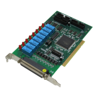
For PCI7250 and PCI-7251, there are 8 jumpers (JP1 to JP8)
associated with each digital input channel for configuring the channel
as AC-Filter or Non-AC-Filter input. Each digital input channel and their
corresponding jumper are shown in the following Table 2.1. Note
JUMPER INPUT SIGNAL
JP1 DI0
JP2 DI1
JP3 DI2
JP4 DI3
JP5 DI4
JP6 DI5
JP7 DI6
JP8 DI7
Table 2.1 The jumper and DI channels
The default setting of the input signal selection is Non-AC-Filter ( DC
signal input), which is shown as below :
JP1
DC AC
Input Signal Selection Non-AC-Filter
(DC Signal)
AC-Filter
(AC Signal)
Jumper JP1 ~ JP8 2-3 1-2
Table 2.2 Input Signal Selection Jumper Setting
 Loading...