2
00000-18-10228P4
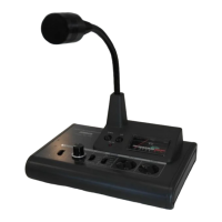
4) Output Level Volume : Use it for control of output level. Adjust it to get an optimum level output. (It has
no concern with compressor control and please adjust the level with monitoring
the meter pointer not to exceed “0dB”.)
5) PTT Switch : Use it for short time QSO. While pressing it, the TX LED Indicator lights up and the
condition is transmitting. (When press it, it sounds 'pip'. When releasing the LOCK
condition also press this switch.)
6) LOCK Switch : Use it for long time QSO. Press it and it sounds ‘peep’. The LED TX indicator③ will
light up continuously. The condition is in transmitting until pressing the PTT switch⑤.
7) UP/DOWN Switch : The same function as the UP/DOWN switch of transceiver. For details, please read
the instructions of transceiver.
8) Level Meter : You can watch the output level of AM-7500E with this meter. Adjust the output
level not to exceed “0dB”. Refer to ④ Output Level Volume and ⑪ Graphic
Equalizer Volume Control. It works also as a battery checker for a few seconds
just after switching the power “ON”.
9) Mic. Output Connector:
(8P ADONIS type)
Connect with suitable conversion cable optionally available to transceiver. (The
conversion cables are provided with a directional condition for connecting. Please
connect with microphone correctly.)
Terminals of Microphone Output Connector ⑨ and “ADONIS” standard terminal
layout (8P) (Fig. 2)
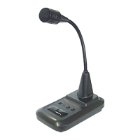
10) Microphone : This model is provided with Condenser type microphone for easy understanding
sound quality.
11) Graphic Equalizer :
Adjustment Volume
The Graphic Equalizer consists of 4 elements with center frequencies 270, 540,
1000 and 2000Hz. The general characteristics including microphone's are designed
as shown on the Fig.3 and you can change the output characteristics freely as
shown on the Fig. 3. If you speak in a low voice tone, turn down the volume of 270
and 540Hz and clear sound quality can be sent to the transceiver. At DX
operation, it is recommendable to slide up the higher tone range, 1000HZ and
2000HZ to get the plain sound quality. When you are in local QSO, turn down the
volume of higher tone range and you can send the soft sound quality. The level
change of each element is about 12dB and when you increase the all elements
12dB Level, the output level of microphone should be increased by 12dB and you
must turn down the output volume accordingly. (The above condition will cause
the distortion.)
12) The Leadwire for canceling the Non-Modulation Prevention Circuit.
①
②
③
④
⑤
⑥
⑦
⑧
E:MIC.EARTH
M:MIC
P:PRESS TO TALK
G:PRESS TO TALK(EARTH)
U:UP
D:DOWN
C:U/D COMMON
B:DC FEEDING(DIRECT CURRENT)
E
M
P
B
G
U
D
1
2
3
4
5
6
7
8
(VIEWED FROM TERMINAL PIN SIDE)
C
 Loading...