When changing pistons use the following procedure:
1. Loosen hex nut located on liquid line and separate
from distributor assembly.
2. Remove the existing piston from inside the distributor
assembly
3. Insert the desired ADP piston into the distributor
assembly.
4. Inspect “O” ring and replace if damaged. Ensure
gasket is in place.
5. Re-install florator nut to body and torque to 10 ft-lbs.
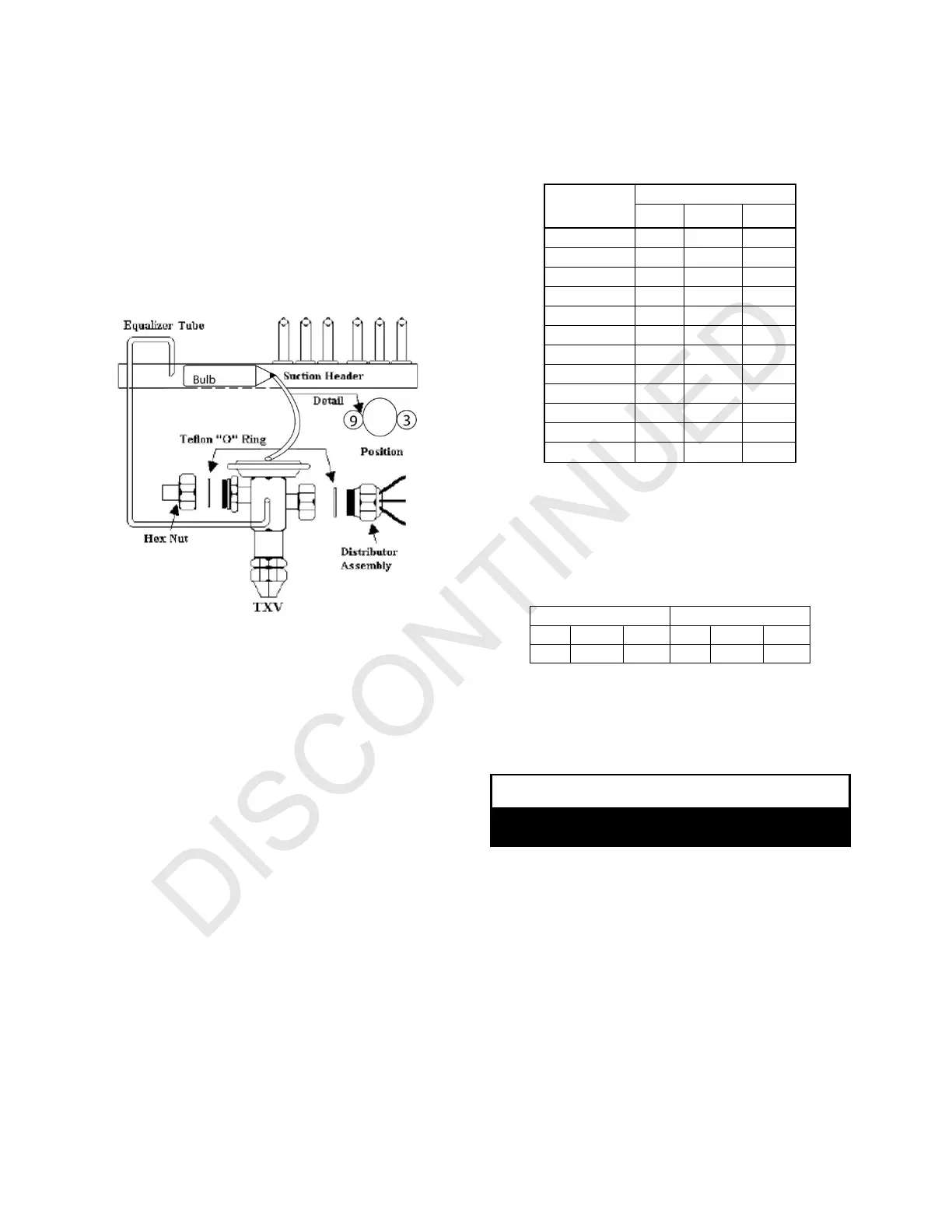
THERMAL EXPANSION VALVES
As shipped from the factory, the TXV installed in each coil is
chosen for the nominal BTUH capacity of
the coil.
If the sensing bulb on the TXV is removed during
installation of the air handler be sure the bulb is relocated to
the suction header as shown above. Wire ties or straps
should be used to hold bulb in position. Cork tape or
insulation wrapped around bulb will improve accuracy of
mechanism.
Field installed TXV kits are also available. Refer to
engineering guide or price sheet for sizes, and kit
instructions for installation procedures.
REFRIGERANT CHARGING INSTRUCTIONS
Outdoor temperature should be 60°F or higher. Set the
system to cooling mode and charge per the applicable
method listed below. For Heat Pump units initially charged
in cooling mode, final adjustment to charge in heating mode
is acceptable if necessary. When charging Heat Pumps in
the heating mode please refer to the outdoor unit’s charging
instructions.
FIXED ORIFICE 1. Run system for at least 10 minutes to
allow pressure to stabilize. 2. Add or recover refrigerant
until the superheat matches the table below.
Outdoor Air
Temp. (°F)
Min Nom Max
EXPANSION VALVE 1. Run system for at least 10
minutes to allow pressure to stabilize. 2. Add or recover
refrigerant until the subcooling matches the table below. 3.
If equipped, adjust the valve until the superheat matches
the table below.
CONDENSATE DRAIN
CAUTION!
Unit is equipped with side and bottom openings. If
bottom openings are not used- they must be plugged!
Determine the drain connections to be used and note the
difference between the primary and
secondary openings.
If side openings are used, use screwdriver to remove
webbing from selected openings.
It is recommended that ¾‘’ male pipe thread PVC fittings be
used at the condensate pan. Do not over-tighten.
Tubing for all condensate drains should be a minimum of
7/8‘’ OD. The drain should be pitched downward 1‘’per 10‘.
Install a 3‘’ trap as close to the coil as possible.
 Loading...