The document describes the FT-DC3-LC Product Guide for a remote start module manufactured by Firstech, LLC. This guide provides instructions for installation, programming, and troubleshooting the FT-DC3-LC module.
Function Description
The FT-DC3-LC is a Remote Start Module designed to add remote start capabilities to a vehicle. It integrates with the vehicle's existing systems to allow for remote engine starting, and can be expanded with various accessories for enhanced functionality such as alarm features, telematics, and additional remote control options. The module is programmable, allowing for customization of its features and outputs to suit specific vehicle requirements and user preferences.
Important Technical Specifications
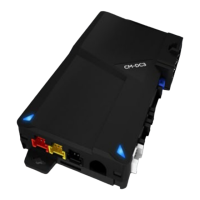
The core component is the CM-DC3 Module, which serves as the central processing unit for the remote start system.
Connectors and Ports:
- M1 - 8 Pin Black: Main power and control connector.
- M2 - 12 Pin Black: Outputs for lock, unlock, trunk release, arm, disarm, GWR, siren, horn, RAP shutdown, ground when armed, and parking lights.
- 01 GREEN BLACK DOT - LOCK (-) OUTPUT
- 02 BLUE BLACK DOT - UNLOCK (-) OUTPUT
- 03 RED/WHITE BLACK DOT - TRUNK RELEASE (-) OUTPUT
- 04 GREEN/WHITE BLACK DOT - ARM (-) OUTPUT
- 05 GREEN/BLACK BLACK DOT - DISARM (-) OUTPUT
- 06 BLUE/WHITE BLACK DOT - GWR (-) OUTPUT
- 07 BROWN BLACK DOT - SIREN (+) OUTPUT
- 08 WHITE/PURPLE BLACK DOT - HORN (-) OUTPUT
- 09 PURPLE/BLACK BLACK DOT - RAP SHUTDOWN (-) OUTPUT
- 10 WHITE/BLACK BLACK DOT - HORN (-) OUTPUT
- 11 BROWN/BLACK BLACK DOT - GROUND WHEN ARMED (-) OUTPUT
- 12 WHITE BLACK DOT - PARKING LIGHTS (-) OUTPUT
- M3 - 10 Pin White: Inputs for brake, e-brake, door, tach, X-trigger, hood, trunk, glow plug, and external alarm sensor.
- 01 BROWN SILVER DOT - BRAKE (+) INPUT
- 02 BLACK/WHITE SILVER DOT - E-BRAKE (-) INPUT
- 03 PURPLE SILVER DOT - DOOR (+) INPUT
- 04 GREEN SILVER DOT - DOOR (-) INPUT
- 05 PURPLE/WHITE SILVER DOT - TACH (-) INPUT
- 06 WHITE/BLUE SILVER DOT - X-TRIGGER (-) INPUT
- 07 GRAY SILVER DOT - HOOD (-) INPUT
- 08 BLUE SILVER DOT - TRUNK (-) INPUT
- 09 GRAY/BLACK SILVER DOT - GLOW PLUG (+) INPUT
- 10 TAN SILVER DOT - EXT ALARM SENSOR (-) INPUT
- M4 - 20 Pin Black: Functions defined by firmware.
- M5 - 6 Pin Blue: Functions defined by firmware.
- M6 - 6 Pin Black: Functions defined by firmware.
- Battery - 2 Pin White
- Drone - 4 Pin Gray
- RF Port - 4 Pin Blue: Connects to RF Kit antenna.
- RPS Sensor - 4 Pin White
- Sensor 2 - 4 Pin Green
- Alarm LED - 2 Pin White
- Temp Sensor - 2 Pin Blue
- Programming Button/LED 2: Used for module programming and diagnostics.
- LED 1: Status indicator.
- FT-DAS - 4 Pin Red
- BLE - 4 Pin Yellow
- FT-DAS Sensitivity Adjustment Dial
- Weblink Port - 4 Pin Black: Used for programming and configuration via Weblink Cable or Weblink Mobile.
Power Specifications (from FT-HRN-DC3-PWR Analog Harness):
- 01 ORANGE - ACCESSORY (+)
- 02 RED - POWER (30A)
- 03 PURPLE - STARTER (+)
- 04 PINK/WHITE - PROG. RELAY #4 - IGNITION 2 (+) (DEFAULT)
- 05 PINK - IGNITION (+)
- 06 WHITE - PROG. RELAY #5 (10A) - PARKING LIGHTS (+) (DEFAULT)
- 07 RED - POWER (30A)
- 08 BLACK - GROUND
Compatibility:
- Compatible with Arctic Start FTX remotes (indicated on packaging).
- Supports a maximum of four (4x) aftermarket remotes per system.
Usage Features
Remote Start Operation:
- Initiated by remote control.
- Requires Tach Programming Procedure to learn the vehicle's engine RPM for proper operation.
- Includes safety features such as shutdown error codes for various conditions (e.g., engine tach signal lost, emergency brake lost, hood open, vehicle moving).
Programming and Configuration:
- Tach Programming Procedure: A 6-step process to teach the module the vehicle's tachometer signal, crucial for reliable remote starting. Involves starting the vehicle, pressing the brake, activating the programming button/remote start button, and observing LED 2 flashes.
- Aftermarket Remote Programming Procedure: A 9-step process to program aftermarket remotes to the system. Involves cycling ignition, observing parking light flashes, and pressing the LOCK button on the remote. A maximum of four remotes can be programmed.
- Valet Mode Programming Procedure: A 6-step process to enable or disable Valet Mode. In Valet Mode, the remote starter is non-functional, but keyless entry, lock, and unlock functions remain active.
- Online Module Settings: The module's configuration options are accessible through Weblink and Weblink Mobile. These include:
- MENU 1 - Remote Starter: RS related configuration options.
- MENU 2 - Doorlock Options: Convenience feature configuration options.
- MENU 3 - Security Options: Alarm activation and settings.
- MENU 4 - AUX function assignments: Set transmitter AUX buttons controls.
- MENU 5 - Programmable outputs (POC): Set actions for programmable outputs.
- MENU 6 - Pulse Timer Output Configuration (PTO): Set duration for pulse timer outputs (if used).
- MENU 7 - Input Configurations: Set inputs for Auto by firmware/Data/Analog.
- MENU 8 - Output Configurations: Set outputs for Auto by firmware/Data/Analog.
Diagnostic Features:
- Module Diagnostics (LED 1 Status): LED 1 provides visual feedback on the module's status during programming, tach programming, remote start, and when the ignition is off.
- Flashing RED: Missing/wrong information, module waiting for more info, or module incorrectly programmed.
- Solid RED: Module waiting for more vehicle information, or module incorrectly programmed.
- Flashing GREEN: Additional steps required, or module correctly programmed and operational.
- Solid GREEN then OFF: Module correctly programmed, or reset in progress.
- OFF: No activity, module already programmed, module at rest.
- Specific GREEN/RED flashes: Indicate tach signal status (Analog, Data, not detected, VTS, assumed start) or system in valet mode.
- Remote Starter Error Codes (Parking Light Flashes): After a remote starter failure, parking lights flash three times, then an additional [X] number of times to indicate a specific error code. Codes cover conditions like engine running, key in ignition, open doors/hood/trunk, brake ON, reservation OFF (manual transmission), tach failure, vehicle moving, valet mode, CAN communication failure, RS not synchronized, and bypass problem.
- Remote Starter Shutdown Error Codes (Parking Light Flashes): If the engine shuts down after a remote start sequence, parking lights flash four times, then an additional [Y] number of times to indicate a specific shutdown error. Codes cover engine tach signal lost, emergency brake lost, foot brake ON, hood open, engine RPM limiter ON, glow plug timeout error, vehicle moving, door open, CAN communication failure, RS not synchronized, takeover not allowed, and board overheat protection.
Maintenance Features
Module Reset Procedure: A 8-step process to reset the module's programming to the vehicle. This procedure does not reset online configured settings. It involves disconnecting and reconnecting specific connectors, pressing the programming button, and observing LED 1. Failure to follow this procedure may result in a DTC (Diagnostic Trouble Code) or CHECK ENGINE error message.
Accessories (Sold Separately):
- Weblink Cable: Required for programming the module via a computer USB port.
- Weblink Mobile: Accessory for mobile device programming via an OBDII connector.
- Telematic Kit (DRONE): For advanced telematics features.
- RF Kit (Antenna): For remote control functionality.
- Alarm Kit (Siren, Alarm LED, FT-DAS): To add alarm features.
- Temperature Sensor: For monitoring vehicle temperature.
- Analog Harness FT-HRN-DC3-PWR: Provides additional power and input/output connections.
- Hood Switch: A safety input to detect if the hood is open.
Important Notices:
- Installation must be performed by a certified technician.
- The manufacturer is not responsible for electrical damage resulting from improper installation.
- A warning sticker is provided to indicate the vehicle is equipped with a remote starter, advising to disable it prior to vehicle maintenance.

![Preview: FLASHLOGIC OEM-AL(RS)-GM8-[FLCAN]-EN](https://data.easymanua.ls/products/878326/200x200/ads-flashlogic-oem-al-rs-gm8-flcan-en.webp)