Mounting and Wiring the Control
2-5
Wiring the AC Transformer
1321 Transformer
Connect the 1321 Transformer to terminals 1 and 2 on the control board. See Wire Run Chart below
for wire size to use. Use 1321CN in Canada.
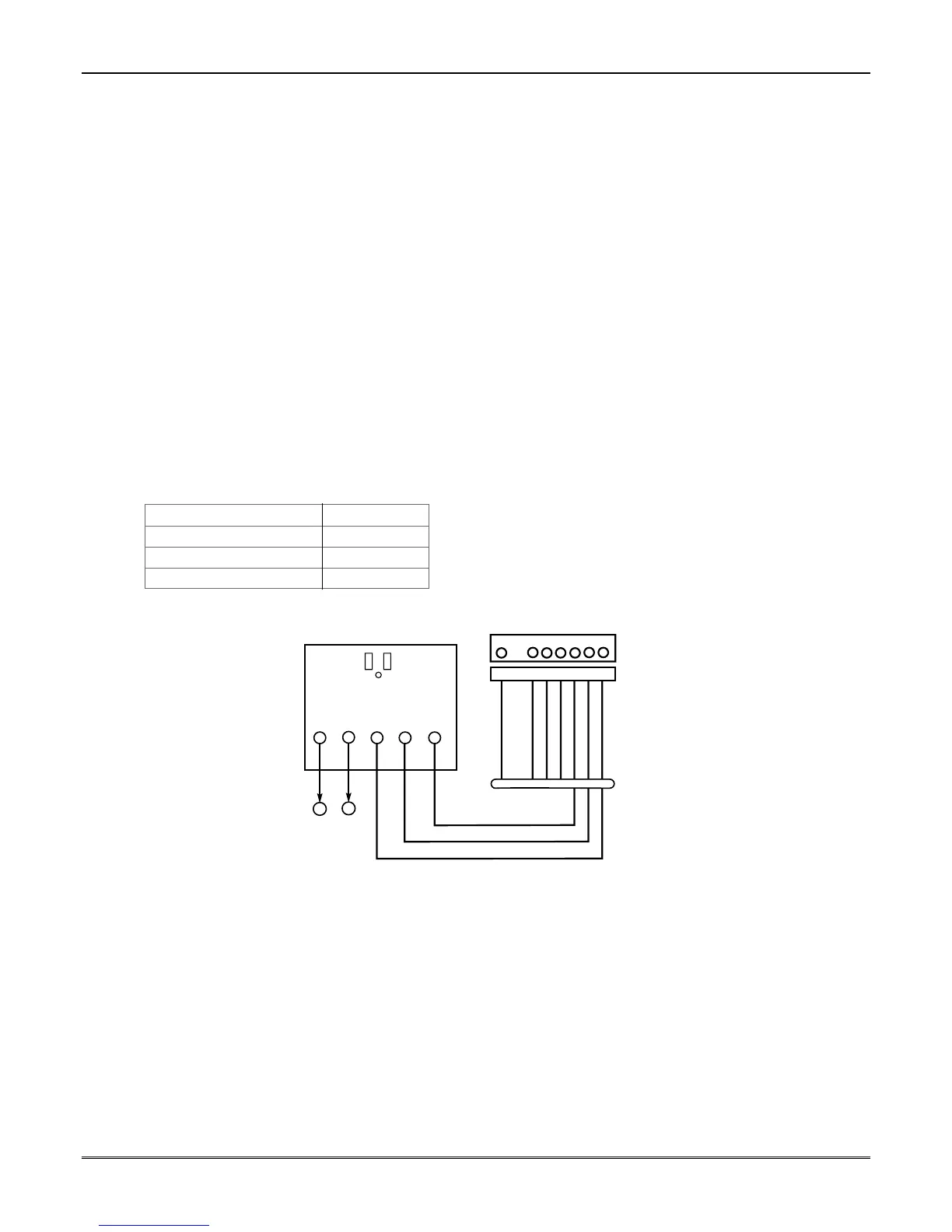
1361X10 Transformer (required if using Powerline Carrier devices)
1. Splice one end of a 3-conductor cable to the wire ends of the SA4120XM-1 Cable.
2. Connect the SA4120XM-1 cable plug to the 8-pin connector on the control (see the Summary of
Connections diagram for location of the 8-pin connector).
3. Connect the other end of the 3-conductor cable to the 1361X10 Transformer, as shown.
Canada: See Powerline Carrier Device section for connections to the PSC04 X-10 Interface and
trigger pins.
Notes
• Use caution when wiring the transformer to the control to guard against blowing the transformer
fuse (the fuse is non-replaceable).
• Wiring to the AC transformer must not exceed 250 feet using 16 gauge wire. The voltage level
between terminals 1 and 2 of the control must not fall below 16.5VAC or else an “AC LOSS”
message will be displayed.
• Do not plug the transformer into the AC outlet while making any wiring connections to the control.
As a safety precaution, always power down the control when making such connections.
Wire Run Chart
Distance from control Wire Size
Up to 50 feet # 20
50–100 feet # 18
100-250 feet # 16
AC AC
SYNC
COM DATA
2
34
5
1
2
1
SA412OXM-1
CABLE
CONTROL
BOARD
TERMS.
1361X10 TRANSFORMER
00-trigcon-001-V2
1 345678
8-PIN TRIGGER CONNECTOR
KEY
+12 AUX.
DATA
COM
SYNC
GND (-)
OUTPUT 17
(RED)
OUTPUT 18
(GREEN)
(ORANGE)
(YELLOW)
(BLUE)
(PURPLE)
(BLACK)
Figure 4. 1361X10 Transformer Connections
 Loading...