EasyManua.ls Logo

ADTRAN MX2820 - User Manual

ADTRAN MX2820
2 pages
Print Icon
To Next Page IconTo Next Page
Loading...
MX2820 23" FAN MODULE
JOBAID
61186006L1-22A
0401
MX2820
23" FAN
MODULE
C A U T I O N C A U T I O N !
SUBJECT TO ELECTROSTATIC DAMAGE
OR DECREASE IN RELIABILITY.
HANDLING PRECAUTIONS REQUIRED.
#61186006L1-22A#
DESCRIPTION
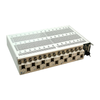
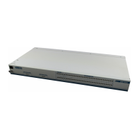
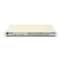
The MX2820 23" Fan Module is a single 1U housing that incorporates a filter, circuit
boards, and fans to provide forced air ventilation for the 23" MX2820 Chassis and all
of its associated modules. It is installed below the MX2820 Shelf and is designed to
cool a single chassis. The MX2820 23" Fan Module:
Mounts directly below a 23" MX2820 Chassis (P/N 1186001L2) and provides
enough forced air ventilation to keep the internal shelf temperature no greater
than 20°C above the external ambient temperature.
Occupies one rack mounting space in a 23" rack and includes all the necessary
brackets and mounting hardware.
Accommodates two power inputs, ±24 V to 48 V (A and B) with one ±24 V or 48 V
return per input.
Should be powered from the rack fuse and alarm panel.
Reports alarms via the MX2820 SCU.
Provides front panel LEDs to indicate status of the fans.
Allows fan and filter replacement from the front without rewiring or removing the
assembly from the rack.
FRONT PANEL LEDS
Pwr/Sfan Green Power on
Yellow One fan or power supply has failed
Mfan Off (Multiple Fan) Power on, all fans OK
Red Multiple fan failures
CONNECTIONS
The MX2820 Fan Module mounts directly under the MX2820 Chassis, P/N 1186001L2
in a 23" rack. It is powered from the rack fuse and alarm panel. The MX2820 Fan
Module Assembly consists of two main units, the fan module and the base assembly.
TURN-UP STEPS
To install the MX2820 23" Fan Module, perform the following steps:
After unpacking the MX2820 Fan Module, inspect it for damage. If damage is found,
file a claim with the carrier, and then contact ADTRAN Customer Service.
Mount the MX2820 Fan Module in the rack immediately below the MX2820 Chassis
with the screws provided.
Disconnect the power source and run power connections to the MX2820 Fan Module
for both A and B power feeds, and terminate them on the power lugs located on the
terminal block on the rear of the chassis. These connections can be made with up to
14 gauge wire and should be fused with 1.5 amp slowblo fuses for 48 VDC and 3 amp
for 24 VDC.
Run connecting wires from the FAN1 and FAN2 wire-wrap pins located near the
power connectors on the MX2820 Fan Module to the Aux3 wire-wrap pins on the right
rear of the MX2820 chassis to connect the fan alarms to the MX2820 SCM Module.
Restore power to the MX2820 Fan Module.
PROVISIONING
There are no provisioning steps other than installing the MX2820 Fan Module and
connecting the power and alarms.
MAINTENANCE
Replacement fans, P/N 1186008L1, are available and can be ordered separately. This
is a plug-in assembly and can be replaced without powering down the chassis.
Minimal routine maintenance of the MX2820 Fan Module is required. The filter
should be inspected for excessive dust at least every 90 days and replaced as needed.
Follow the steps below to replace the filter:
1. Loosen the two screws on either side of the front panel of the MX2820 Fan Module.
2. Carefully remove the front panel, taking care not to disturb the filter.
3. Remove the old filter carefully, taking care not to allow dust from the filter to enter
the system.
4. Install a new filter, P/N 1186009L1.
5. Replace the front panel.
6. Tighten the screws to secure the front panel to the MX2820 Fan Module.
OPERATIONAL SPECIFICATIONS
Operates from A or B ±24 V or 48 V input voltage power feeds.
For 48 VDC (nominal) use a 1.5 A fuse. For 24 VDC (nominal) use a 3 A fuse.
Operates over temperature range of (0°C to +50°C)
Storage 40°C to +70°C. Relative humidity to 95 percent, noncondensing.
1186006L1
PWR=GRN
SFAN=YEL
MFAN
ORDER REPLACEMENT FILTER NO. 1186009L1
1
2
3
4
5

Other manuals for ADTRAN MX2820

Question and Answer IconNeed help?

Do you have a question about the ADTRAN MX2820 and is the answer not in the manual?

Summary

MX2820 23 Fan Module Description and Features

Front Panel LED Indicators

Status indicators for power and fan operation, including green, yellow, and red light meanings.

Installation and Turn-Up Procedures

Provisioning and Maintenance

Filter Replacement Procedure

Steps for removing and installing a new fan module filter without powering down.

Operational and Compliance Specifications

Compliance Standards and Grounding

Details on UL, NEBS, GR-1089-CORE compliance and DC grounding system requirements.

Product Warranty Information

Overview

The ADTRAN MX2820 23" Fan Module is a single 1U housing designed to provide forced air ventilation for the 23" MX2820 Chassis (P/N 1186001L2) and its associated modules. It is intended to cool a single chassis and mounts directly below the MX2820 Shelf. The module ensures that the internal shelf temperature remains no greater than 20°C above the external ambient temperature.

Function Description

The MX2820 23" Fan Module integrates a filter, circuit boards, and fans within its 1U rack-mounting space. It accommodates two power inputs, either ±24 V or -48 V (A and B), with one ±24 V or -48 V return per input. The module is powered from the rack fuse and alarm panel and reports alarms via the MX2820 SCU (System Control Unit). Front panel LEDs indicate the status of the fans, providing immediate visual feedback on the module's operational health. The design allows for both fan and filter replacement from the front, eliminating the need for rewiring or removing the entire assembly from the rack.

Important Technical Specifications

  • Power Input: Operates from A or B ±24 V or -48 V input voltage power feeds.
  • Fusing: For 48 VDC (nominal) use a 1.5 A fuse; for 24 VDC (nominal) use a 3 A fuse.
  • Operating Temperature Range: 0°C to +50°C.
  • Storage Temperature Range: -40°C to +70°C.
  • Relative Humidity: Up to 95 percent, noncondensing.
  • Mounting: Occupies one rack mounting space in a 23" rack and includes all necessary brackets and mounting hardware.
  • Power Connections: Supports up to 14 gauge wire for power connections, fused with 1.5 amp slow-blow fuses for 48 VDC and 3 amp for 24 VDC.
  • Compliance: Evaluated to UL 60950, NEBS Level 3, and GR-1089-CORE compliance. Intended for use in restricted access areas and to be installed in a type "B" or "E" enclosure.
  • Grounding: The MX2820 Fan Module Frame Ground terminal must be connected to an earth ground. It is designed for installation in a DC-C (common) bonding and grounding system, with the chassis ground wire having equal or greater ampacity than the wire connected to the -48 VDC or ±24 VDC return. It is not designed for installation in a DC-I (isolated) bonding and grounding system.
  • FCC Compliance: Complies with Part 15 of the FCC rules, subject to the conditions that it does not cause harmful interference and accepts any interference received.

Usage Features

  • Easy Installation: Mounts directly below the MX2820 Chassis using provided screws.
  • Alarm Integration: Connects to the MX2820 SCM Module via wire-wrap pins (FAN1 and FAN2 on the fan module to Aux3 on the chassis) to provide fan alarms.
  • Status Indicators: Front panel LEDs provide clear status:
    • Pwr/Sfan (Green): Power on.
    • Pwr/Sfan (Yellow): One fan or power supply has failed.
    • Mfan (Off): Power on, all fans OK (Multiple Fan).
    • Mfan (Red): Multiple fan failures.
  • Modular Design: The assembly consists of two main units: the fan module and the base assembly, facilitating maintenance.
  • No Provisioning Steps: Once installed and connected, no further provisioning steps are required.

Maintenance Features

  • Fan Replacement: Replacement fans (P/N 1186008L1) are available as a plug-in assembly and can be replaced without powering down the chassis.
  • Filter Replacement: The air filter (P/N 1186009L1) should be inspected for excessive dust at least every 90 days and replaced as needed. The process involves:
    1. Loosening two screws on the front panel.
    2. Carefully removing the front panel.
    3. Removing the old filter, taking care to prevent dust from entering the system.
    4. Installing a new filter.
    5. Replacing the front panel.
    6. Tightening the screws to secure the front panel.
  • Front-Access Maintenance: Both fan and filter replacements can be performed from the front of the unit, simplifying maintenance procedures and reducing downtime.
  • Warranty: ADTRAN offers a 5-year warranty for replacement or repair if the product does not meet specifications or fails in service.

ADTRAN MX2820 Specifications

General IconGeneral
BrandADTRAN
ModelMX2820
CategoryMultiplexer
LanguageEnglish

Related product manuals