Do you have a question about the ADTRAN MX2800 and is the answer not in the manual?
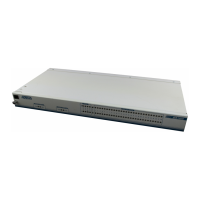
Provides a description of the MX2800 multiplexer and its capabilities.
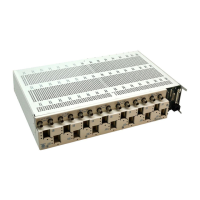
Details the hot-swappable controller cards for 1:1 redundancy.
Explains the T3 bandwidth and its cost-effectiveness for data and voice.
Describes SNMP and Telnet for configuration, monitoring, and diagnostics.
Lists optional hardware like Breakout Panel and Battery Backup.
Guides on receiving inspection, unpacking, and powering on the device.
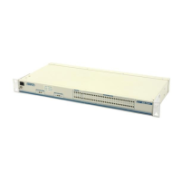
Instructions for mounting the MX2800 unit into a standard equipment rack.
Details the various ports and connectors on the rear of the MX2800 unit.
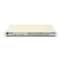
Describes the components and indicators on the MX2800 front panel faceplate.
Procedure to connect to the MX2800 via a VT 100 terminal for configuration.
Explains the meaning of LEDs for power supplies, controller cards, and T1/E1 status.
Configures DS3, DS2, and other network interface parameters.
Configures T1/E1 state, coding, length, loopback, and protection.
Sets up 1:1 protection against hardware or network failures.
Configures SNMP, Telnet, security, and alarm settings for system management.
Accesses system info, updates software, resets the system, and saves configuration.
Displays current state of the DS3 network interface, including framing and alarms.
Indicates the installed power supply types and their current operational state.
Shows alarms and state for controller cards, including failures and switches.
Displays the current state of individual T1s or E1s, including OK, LOS, XCV, etc.
Accesses menus for alarm history and performance parameters for DS2s and T1/E1s.
Provides alarm history and performance parameters for DS3 links.
Provides alarm history and performance parameters for DS2 links.
Provides alarm history and performance metrics for T1/E1 links.
Performs various loopback tests on T1/E1 lines for troubleshooting.
Executes loopback tests on the DS3 interface for network verification.
Conducts loopback tests on the DS2 interface to diagnose issues.
Describes operation with a single controller card and network connection.
Provides backup for controller card failure, allowing continued operation.
Offers complete backup for both controller card and network failures.
Describes operation with a single power supply and source.
Enables continued operation during a single power supply card failure.
Details the battery backup system for operation during power outages.
Details the pin assignments for the craft port connector.
Details the pin assignments for the LAN port connector.
Details the pin assignments for the modem port connector.
Lists channelized DS3, line length, framing, and line rate specifications.
Lists line length, line rate, line code, and interface connector specs.
Details VT 100, SNMP/Telnet, and modem interface specifications.
Lists FCC, Industry Canada, UL, CUL, and NEBs compliance standards.
Contact information for sales and applications engineering inquiries.
Contact details for technical support and post-sale inquiries.
Outlines the process for returning equipment for repair, including RMA procedures.
| Data Rate | 1.544 Mbps (T1), 2.048 Mbps (E1) |
|---|---|
| T1 Line Code | AMI, B8ZS |
| T1 Framing | D4, ESF |
| Type | Multiplexer |
| Interface | T1 |
| Management | SNMP, Web-based, CLI |
| Form Factor | Rack-mountable |
| Power Supply | AC or DC options available |
| Operating Temperature | 0°C to 50°C |