Appendix A. Pinouts
A-2 MX2800 User Manual 61200290L1-1
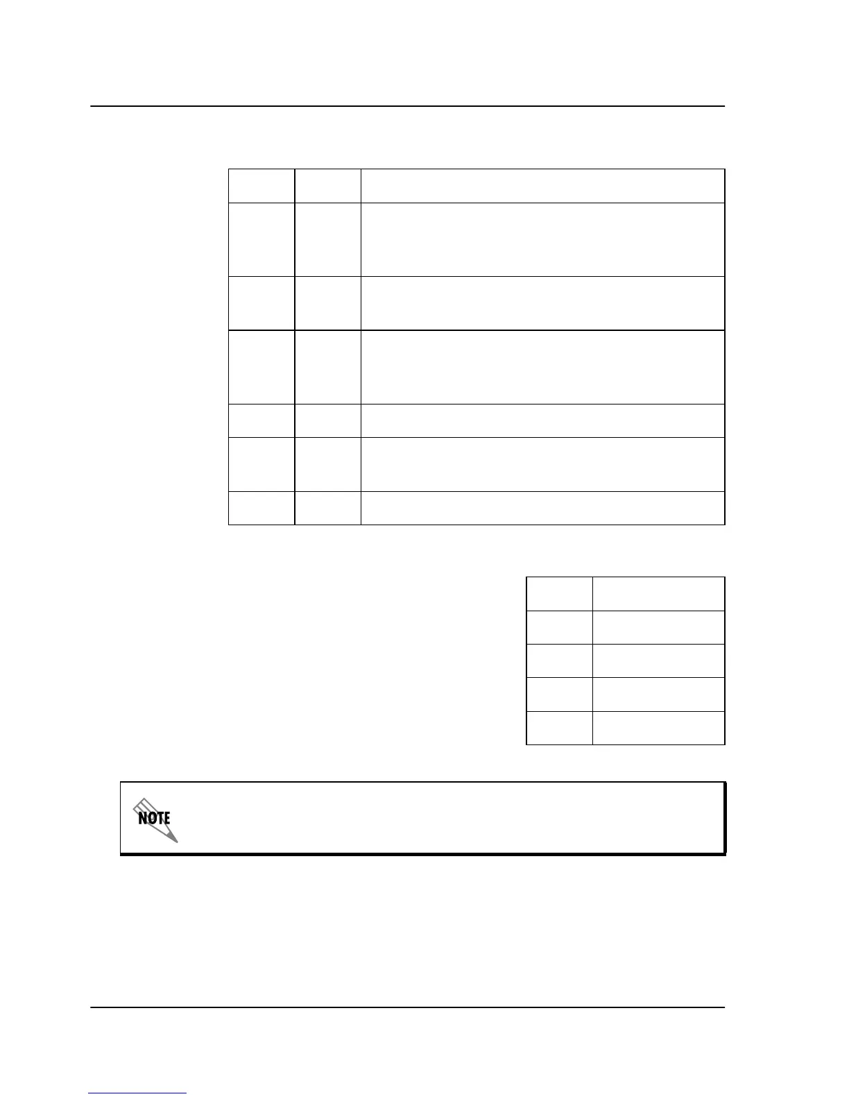
Table A-2. LAN Port Pin Assignments
Table A-3. Modem Port Pin Assignments
Pin Name Description
1 TD+ The positive signal for the TD differential pair.
This signal contains the serial output data
stream transmitted onto the network.
2 TD- The negative signal for the TD differential pair
(pins 1 and 2).
3 RD+ The positive signal for the RD differential pair.
This signal contains the serial input data
stream received from the network.
4, 5 N/A Not used.
6 RD- The negative signal for the RD differential pair
(pins 3 and 6).
7, 8 N/A Not used.
Pin Description
1, 2, 3 not used
4Tip
5Ring
6, 7, 8 not used
The modem port pin assignments apply to units equipped with an inter-
nal modem (4200290L1, L2, L3, and L4).