Chapter 2. Installation and Operation
2-6 MX2800 User Manual 61200290L1-1
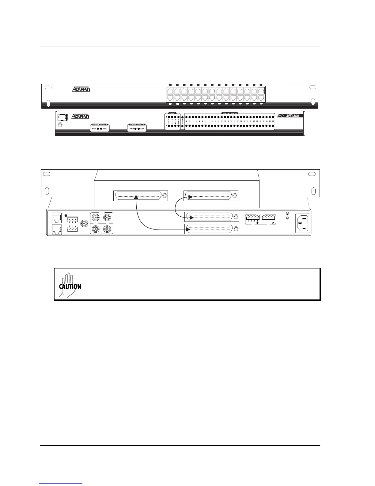
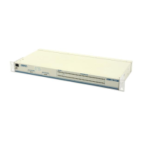
Figure 2-2. The Breakout Panel
REAR PANEL
The MX2800 rear panel is equipped with a LAN port, a modem
port, two alarm output terminal blocks, an external clock interface,
two sets of DS3 in/out jacks, two Amphenol (Amp) connectors,
and DC/AC power connections. Figure 2-3 illustrates the rear
panel and identifies its equipment. Descriptions for these items
follow the figure. Pin assignments are given in Pinouts on page A-1.
L
A
N
M
O
D
E
M
CRITICAL
NO COM NC
NONCRITICAL
EXT CLK
DSX-3
IN
OUT
A
B
DSX-1/E1
(OUT)
DSX-1/E1
(IN)
USE COPPER
CONDUCTORS ONLY!
PWR
FAIL
RET
RET
PWR
FAIL
AB
DC POWER
115VAC 50/60HZ
0.8a
IN OUT
1 3 5 7 9 11 13 15 17 19 21 23 25 27
2 4 6 8 10 12 14 16 18 20 22 24 26 28
Cable 1
Cable 2
Rear View
Front View
To properly ground the breakout panel, expose the contact points’ bare metal prior
to installation. Do this by scraping the paint from the portion of the panel’s
mounting ears that makes contact to the rack.