Chapter 2. Installation and Operation
2-8 MX2800 User Manual 61200290L1-1
Modem Port
The MODEM port is an 8-pin modular jack that provides a telephone
line (POTS) connection for the internal V.34 modem.
The MX2800 can be configured as a dial-in host and also as a dial-
out-on-Trap device (meaning that the unit dials out to a specified
host to report error conditions). Configure the modem parameters
in the
D
IALUP
O
PTIONS
menu under the
S
YSTEM
M
ANAGEMENT
portion of the
C
ONFIGURATION
menu (
C
ONFIGURATION
->
S
YSTEM
M
ANAGEMENT
->
D
IALUP
O
PTIONS
). See Dialup Options on page 3-13.
Noncritical and Critical Alarm Connectors
The alarm connectors connect to the three contacts of a Form C type
relay on the main board of the MX2800. This relay is activated any
time the MX2800 detects an alarm condition on the T3 network
interface. Both
NC (normally closed) and NO (normally open)
contacts are provided.
Connect alarms first to one of the three-position modular terminal
lug connectors (provided). These connectors make it easier to
perform initial wiring and to connect and disconnect alarms when
replacing rackmount units. Once a modular connector is wired,
push it firmly into the rear panel
NONCRITICAL or CRITICAL
connector.
The alarm functions can be enabled or disabled through the
A
LARM
R
ELAYS
section of the
C
ONFIGURATION
menu (see the section Alarm
Relays on page 3-16).
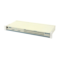
DSX-3 Interfaces
The DSX-3 network interfaces are full-duplex circuits provided by
four BNC coaxial cable connections (two for each controller card).
Information regarding the built-in modem applies to the following list of
numbers: 4200290L1, L2, L3, and L4.