Chapter 3. Configuration
3-16 MX2800 User Manual 61200290L1-1
Alarm Relays
Alarm Relay Configuration
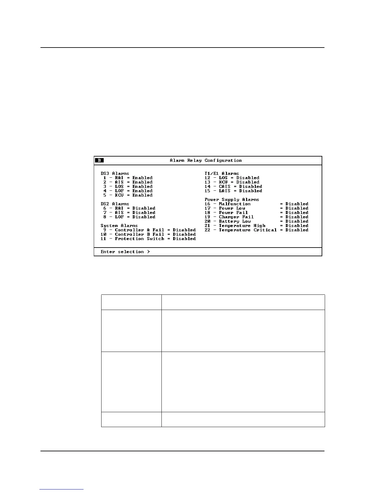
Enables audible and visible alarms for specific error conditions (see
Figure 3-14). The following charts describe the alarm conditions
found in this menu. Conditions marked in the charts with an
asterisk (*) sound the critical alarm when enabled. All other
conditions sound the non-critical alarm.
Figure 3-14.
Alarm Relay Configuration Menu
DS3 Alarms
Alarm Description
RAI* The unit is receiving an RAI (yellow) alarm from
the network. This alarm is a signal sent back to-
ward the source of a failed transmit circuit. The
X-bits (X1 and X2) are set to zero.
AIS* The unit is receiving an AIS (blue) alarm condi-
tion from the network. AIS alarms occur when
consecutive 1010s are received in the informa-
tion bits. This indicates that there is a transmis-
sion fault located either at or upstream from the
transmitting terminal.
LOS* The unit has lost the network Rx signal.